Thinking about giving this a go …
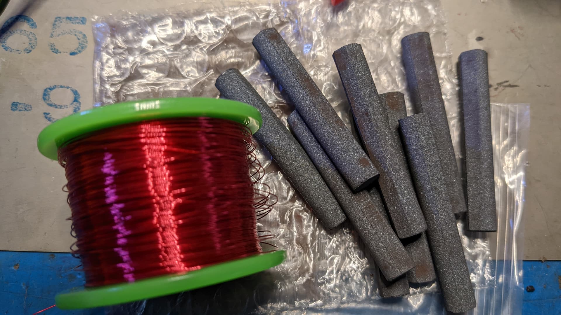
How would 8mm or 10mm ferrite core do compare to the 9mm (8 & 10 are much more available than the 9 to me)?
1/2in (12.7mm) seam to be common here too, but that seem big …
Thinking about giving this a go …
How would 8mm or 10mm ferrite core do compare to the 9mm (8 & 10 are much more available than the 9 to me)?
1/2in (12.7mm) seam to be common here too, but that seem big …
Plus
Although @ODaily says
if you start at the top post, he gives you a very good starting point
Good timing, me and @darthdomo we’re just talking about throwing one of these together
Huhhh???
We might need to reboot Pilgrimsmaster, and/or defrag his harddrive.
Glitchy AI today,
Wargames tomorrow.
“How about a nice game of chess?”
Haha, oops, @compgeek says

What proxmark do you have? Any way you could measure the resistance of it’s stock coil or count the turns and dimensions?
@Pilgrimsmaster thanks for the link, I’ll check out the calculator ![]()
I’ll also go back through the thread to see if I missed anything
That’s a good idea … thanks
Feel dumb for not thinking of it ![]()
Stupid question for those more knowledgeable, as usual
The materials aren’t all that expensive, and even though I don’t 100% understand the process yet… it doesn’t seem terribly difficult
Would there be much variance in the antenna from 1 prox easy to the next?
I was thinking if I wind up making one in the next month l, maybe I can make a few more and sell them for a few bucks over materials to anyone that wants one… and helps to off set needing to buy the LCR meter
But if each antenna needs ti be tuned for each proxmark, that’s a nogo
My guess is that they use the same components on every Proxmark3 easy (or similar) so the differences will be due to variations within the tolerance of those components (capacitors/resistors). The antenna coils are (I am guessing) for ed around a standard former and are all the same size.
So, while an antenna built for your PM3 easy might be perfectly tuned for you, it might not be for me, but should be close enough (within tolerances) that it will work.
Okay one way to find out I guess,
Buying the stuff to build one will give me enough material to build a couple…
So maybe I’ll do that and send to someone to see what it do
Only thing I don’t understand, is the resistor component…
Do I need one? Do I not? And which one?
It’s an easy enough process and should work better than stock on most, but now that the PM3 easy is cloned by so many people with an unimaginable number of small hardware tweaks theres just no way to know if one capacitor in the tuning circuit is different between yours and mine.
That said, cheap enough to give it a shot i guess
@Compgeek
So can you explain the resistor portion of the setup?
I understand get lcr meter, and wrap until it reads what I want
The resistor I don’t understand
Also, would screw hole crimp connectors you used add or effect tuning?
Just trying to make a game plan before I pull the trigger
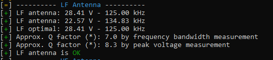
The resistor is used to increase resistance and reduce the voltage. If the proxmark3 claims 75V at 125KHz then you risk damaging a chip. So you add a resistor to drop that voltage to something safer.
Ok that makes sense to a degree…
High voltage bad,
Resistor lowering voltage, good
Is there any way to know what resistor I’d need ahead of time? Sick of having to order things after the fact…so I’d like to order what I need all at once
But I’m guessing it’s not going to work like that
Also, is the resistor going to throw the tuning out of wack when you reduce voltage?
Worry about getting the hz right and then fixing voltage and it messing up the hz and back and forth
An antenna within a uH of the target should operate on any proxmark easy. They do have minor manufacturing differences. Ultimately though it’s not like a passive RFID tag where the component values determine the tuning range. The Proxmark outputs a 13.56MHz signal no matter what. The difference between antennas that causes that voltage difference that Zwack mentioned, and the need for a resistor “sometimes” is due to the impedance of the antenna.
Impedance is just like resistance, but it adds a bit for the resistance of capacitors and inductors. Those values (reactance) change with frequency. Luckily we’re always at 13.56MHz in this situation, so it doesn’t vary. For the stock proxmark antenna they select an inductance value given the available antenna dimensions which “adds” resistance, and capacitance values which “subtract” resistance.
They don’t usually add actual resistors, because that limits the wattage of the antenna. What they usually do is if the impedance is too low (which causes the voltage to be too high) they’ll use thinner gauge wire which inherently has more resistance. Skin effect
Ok, it’s starting to come into focus a bit…
So then is there an advantage of using on size wire over another in this situation? Or should I maybe get slightly thinner wire to start with?
Too thin of a wire and you’ll get too high of a resistance … And there isn’t much you can do at this point …
A bit too big and you can add a resistance …
I used 30awg and don’t need a resistance at all, made a second antenna to confirm and have the same results …
Weird, I thought @Compgeek used .25mm enamel wire which comes out to 30awg unless I missed something obvious
And he seemed to have high voltage
Weird but I guess I’ll order 30 awg and hope for the best
So to confirm, should I or should I not actually order an lcr meter? A few mentioned it’s use, but it looks like people where just adjusting based on what the proxmark said anyways
Thoughts?