That’s why I went with 30awg … But both of my antenna come up to between 24 and 28 volts, so I call that good enough … And get much better reads …
Well … I have one but didn’t used it for this …
Buuuuttttt … It’s a good tool to have on hand if you’re working with any kind of electronic, so maybe get one at some point …
Personally I don’t end up using my LCR meter for anything 13.56MHz because the Henry and Farad values are so small at this frequency range and it’s not accurate enough. I end up using my VNA for everything. You shouldn’t need that though, if the Proxmark reads too high a voltage just add turns. Too low subtract
Did you wind up going with 8mm rod instead of compgeeks 9mm?
(I think I’m looking at the same listing your might have ordered… given the number and lengths)
Could that be why you have better voltages? Caveman thinking hard noises
Thinner core, the less it increases inductance or whatever… so you need more wraps… and longer wire… more resistance so better voltage?
Different ferrites have very different properties, and nobody has any fucking clue what “relative permeability” is so distributors just say “it’s ferrite!”. Compgeek probably ordered a lower permeability ferrite, which means the inductance was lower, which means the inductance’s contribution to the impedance was lower, which means more voltage perceived by the Proxmark
Unless you want to go to great length to measure the properties, just try and make it like compgeeks and see what happens. Now you know what changes would tweak it, so you can adjust the coil once you have a reference point
The ones I got are 8mm/0.3" OD
They clearly have no idea what it is … The description is actually pretty funny:
Description
Description
Specification:
Material: MnZn-ferrite
Diameter: 8mm/0.3’’
Length: 50mm/2’’
Use for Antennas
Quantity: 10pcs
Feature:
Ferrite rod material with flattened profile, for medium and high frequency circuit, antenna
Suitable for Crystal Radio,transformer,etc.
May be cut to size as required.
Application range:
Widely used in color TV, cell phones, monitors, electric vehicle charger, alarm, DVD, switch power supply, power up, DC-DC converter, high-frequency transformer, filter, inductor, household appliances, industrial automation, instrumentation, communication, medical equipment, energy saving lamps and lanterns and so on.
Package Include:
10pcs x Ferrite Rod
Notice:
1.Please allow 1-3mm error due to manual measurement. Pls make sure you do not mind before you bid.
2.The color may have different as the difference display,pls understand.
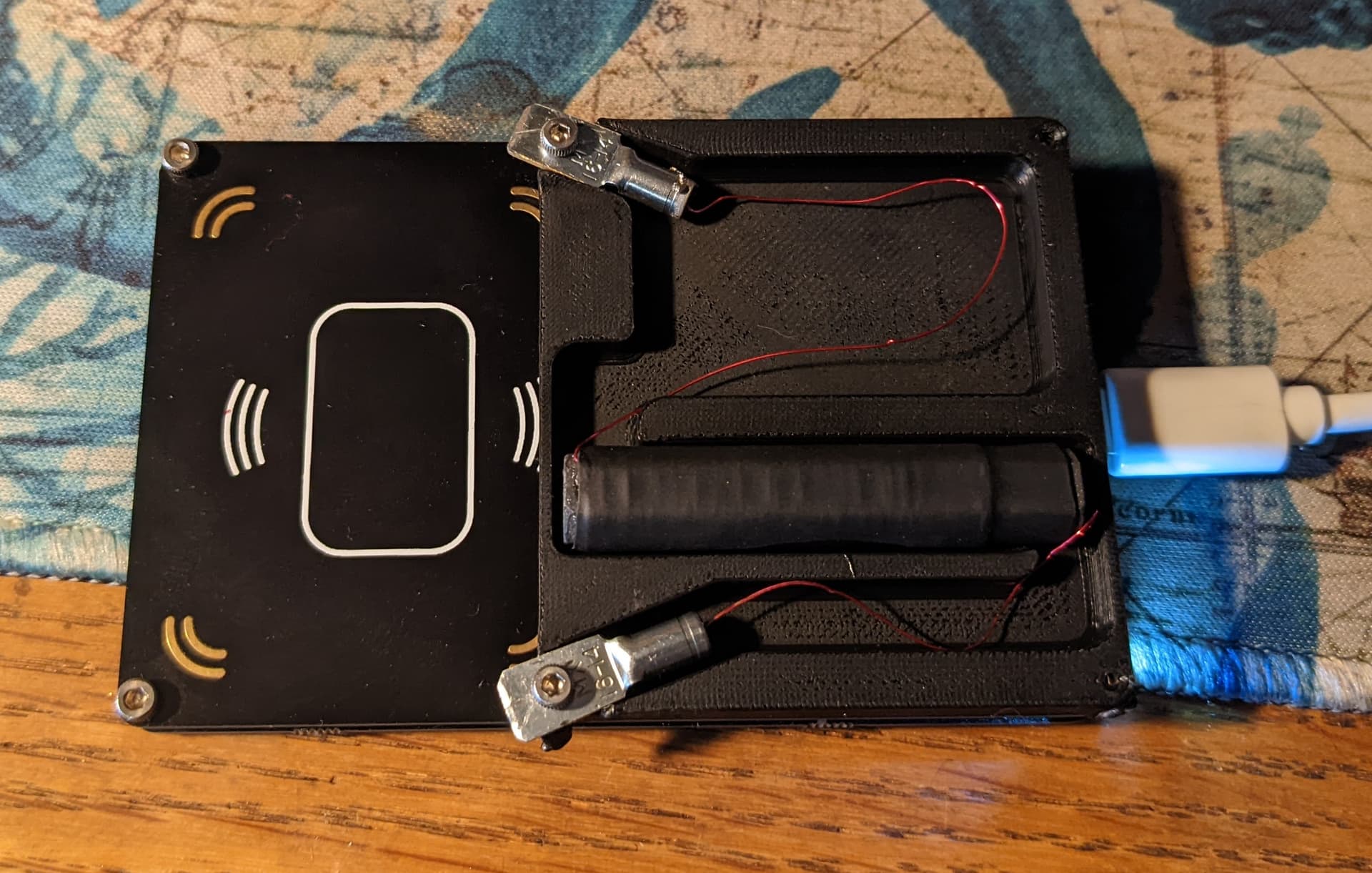
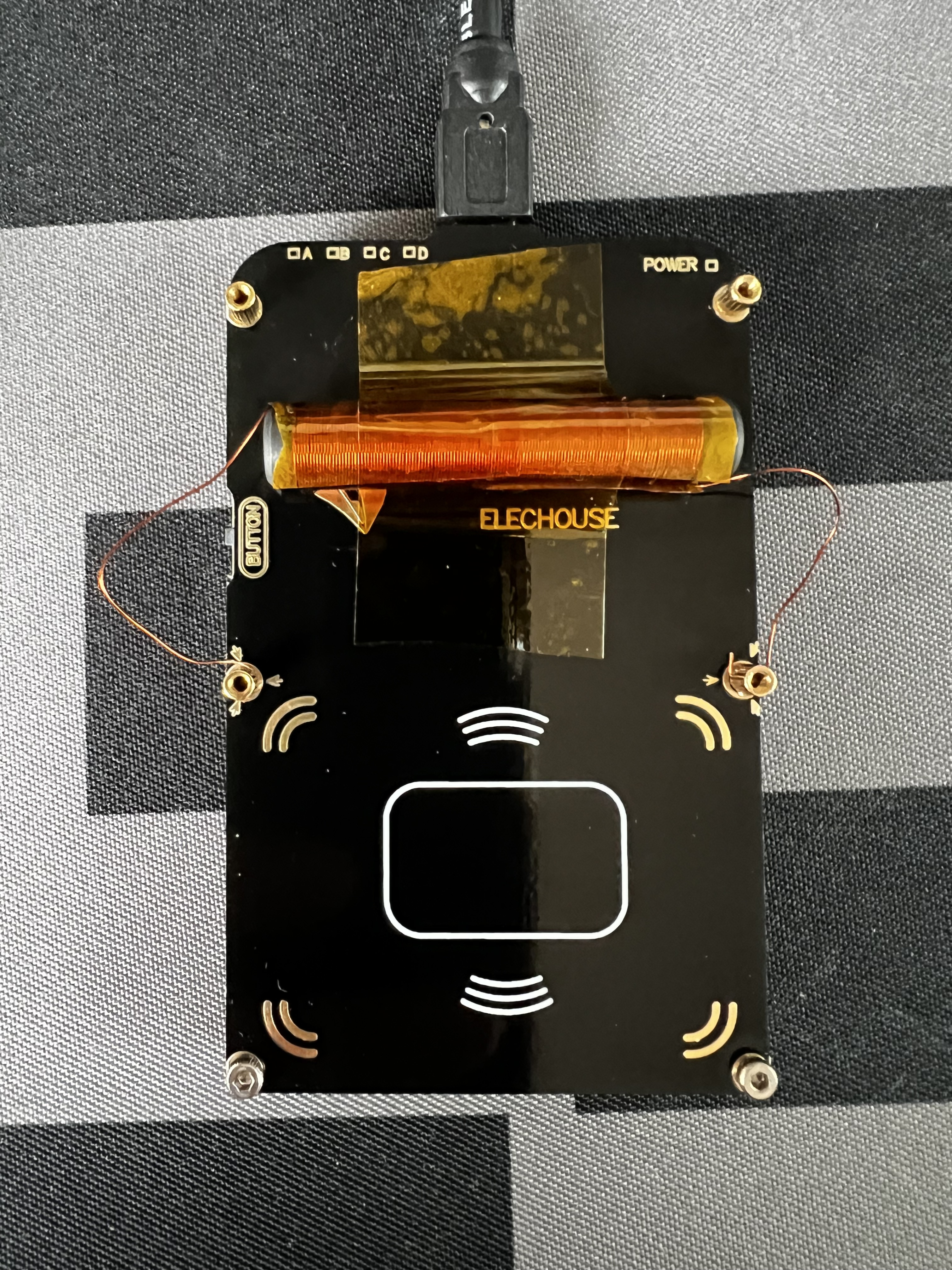
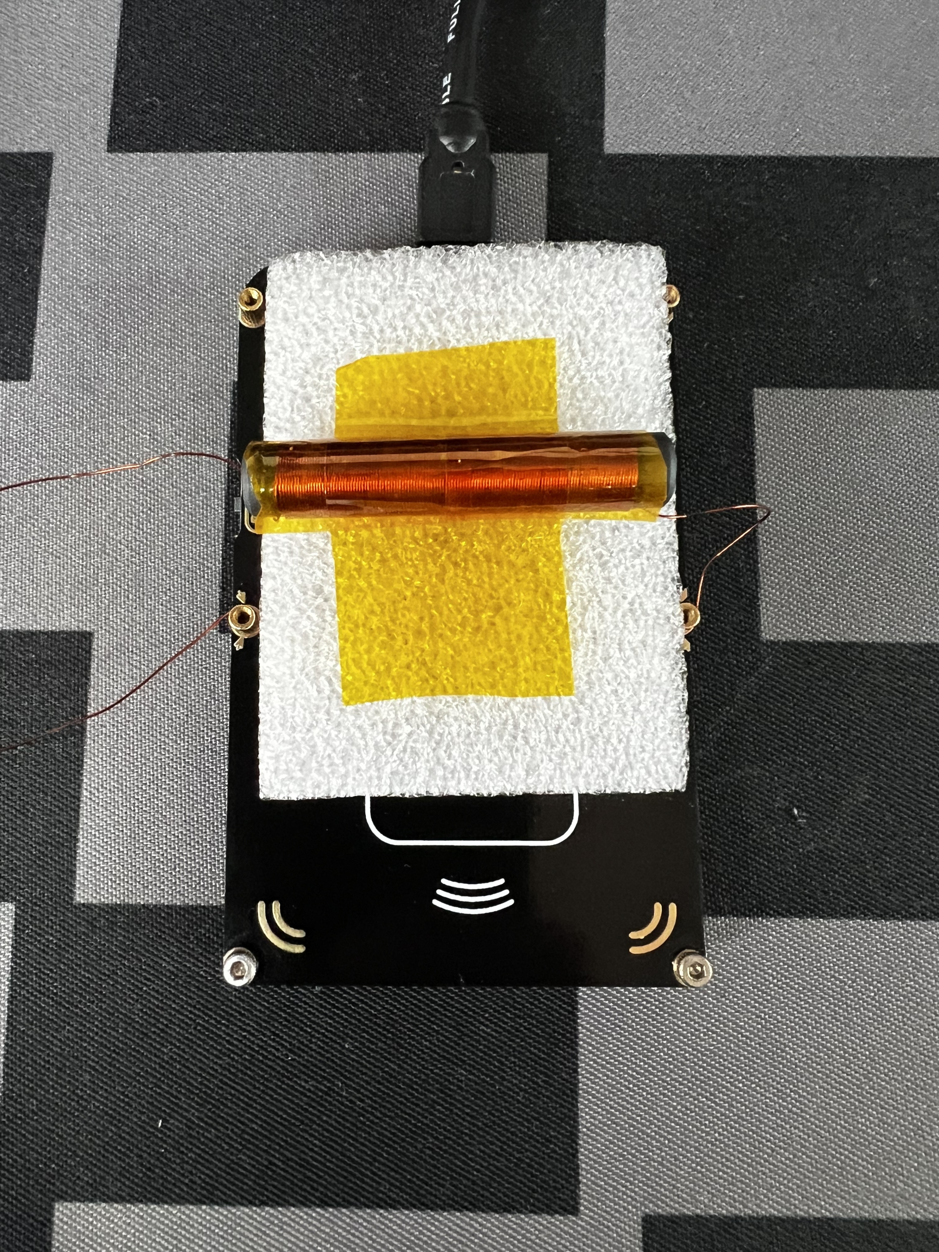
Ps: I’m not sure how to do the fancy fold down … Clearly used the wrong thing …
But is there anything drastic I’m missing at the idea of making a coil for the HF antenna?
Currently very disappointed in hf performance, more so than stock lf
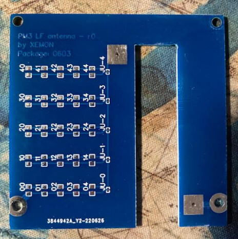
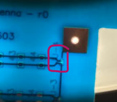
I get that it’s a pcb trace, and harder to attach
But I was thinking breaking the trace right before it goes into the coil, and soldering on coil leads?
You select the big block of text and then from the gear icon choose hide details…
Like this
Description
Specification:
Material: MnZn-ferrite
Diameter: 8mm/0.3’’
Length: 50mm/2’’
Use for Antennas
Quantity: 10pcs
Feature:
Ferrite rod material with flattened profile, for medium and high frequency circuit, antenna
Suitable for Crystal Radio,transformer,etc.
May be cut to size as required.
Application range:
Widely used in color TV, cell phones, monitors, electric vehicle charger, alarm, DVD, switch power supply, power up, DC-DC converter, high-frequency transformer, filter, inductor, household appliances, industrial automation, instrumentation, communication, medical equipment, energy saving lamps and lanterns and so on.
Package Include:
10pcs x Ferrite Rod
Notice:
1.Please allow 1-3mm error due to manual measurement. Pls make sure you do not mind before you bid.
2.The color may have different as the difference display,pls understand
PS: Well, used it on the field today and it performed great, read the NExT instantly and flawlessly.
This is really the best thing you can do to your PM3 if you have a glassy …
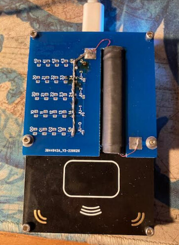
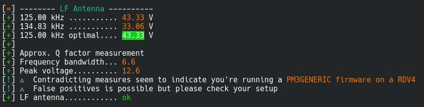
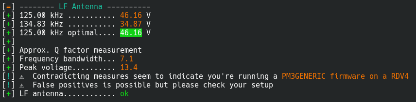
I’ve just had a go at putting together my own bar antenna for my PM3 Easy. It seems resonant on 125kHz and the Q seems similar to the stock antenna according to hw tune.
Unfortunately performance isn’t what I’d hoped for. It does work, but reads are about as unreliable as they were with the stock coil.
My implant is an xMagic and reads well on the doors around my office and my flipper zero (when positioned correctly). I currently have it in EM4100 mode.
Should I be concerned about the ‘contradicting measures’ warning (which I also get with the stock coil)?
Thats SRAM to point to a firmware mismatch
Can you post a screenshot of your opening prompt of the pm3?
I have gotten similar results and will be diving back in this project to see what I can do.
Are you in the US?
I can send you a test board to mount your antenna and see if/how it helps. It’s not gonna be pretty, but it’s a test I’d love some feedback/tester; if it works and I run a batch, I’ll send you a clean board