When planning a placement I print out the silhouettes of implants, cut them out and apply them to my skin with a paper glue stick. (Oh, I’m the freak?! You pervs stab yourselves and stuff the holes with microchips!)
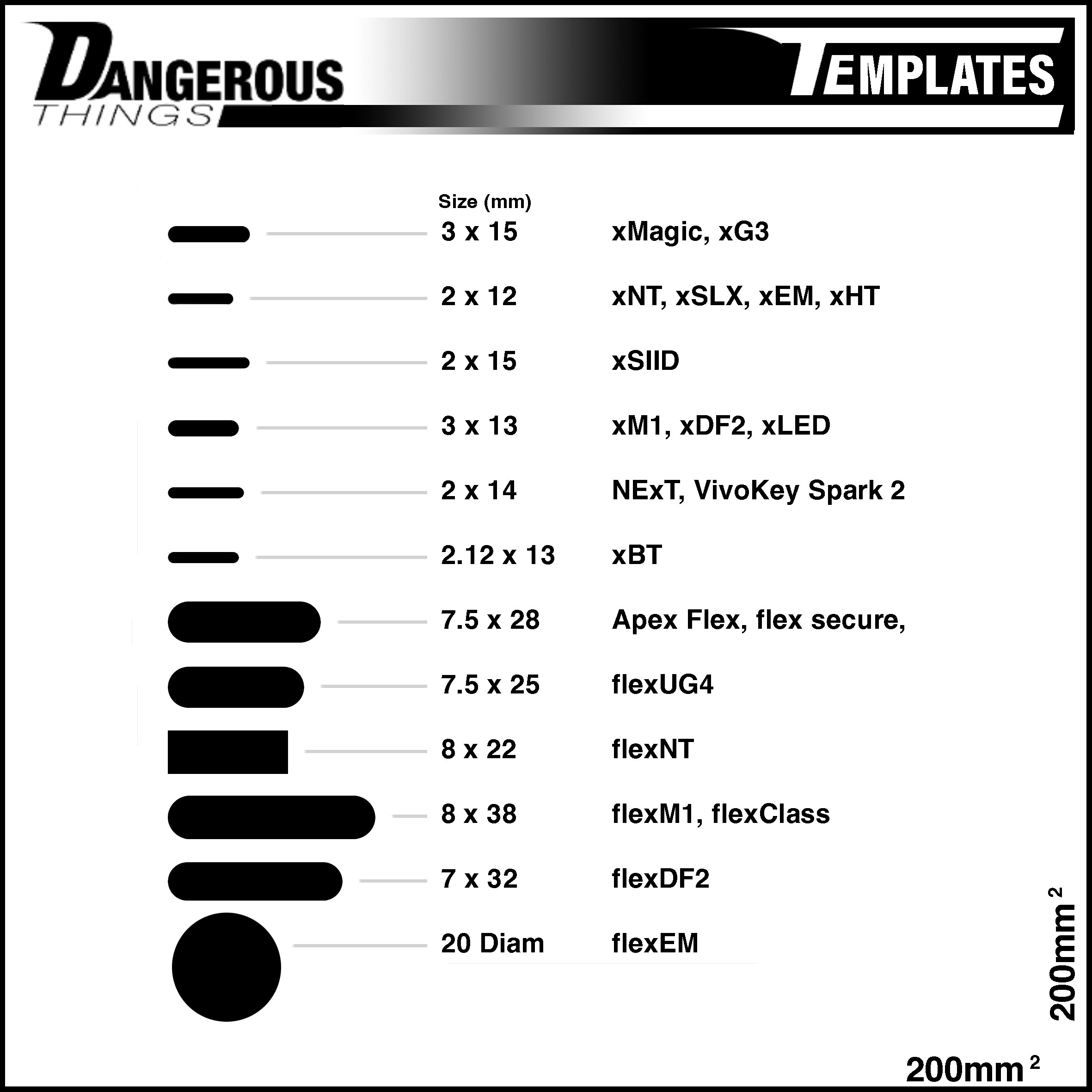
I was doing this today and thought “I wonder if anyone else would find this useful…” so here it is, DT’s current product line in template form.
When you print it you have to check that the external box measures 200x200mm and make adjustments with a graphics app if your printer distorts it.
Haha I have something called my “desk list” and that’s all the things that need doing that can be done most efficiently while at my command center desk with my big screens and fancy keyboard. This is on my desk list.
Unfortunately getting to my desk on the weekend involves battling through a myriad of household projects and child tending tasks that I often succumb to by days end, leaving no energy left to achieve command center nirvana.
I did but decided against it because the Titan is far more three-dimensional. Placement is not as simple as its silhouette. Orientation is as important as placement and would be hard to represent with a flat little circle of paper. If you guys want it I’ll add it but I think it would be misleading, or at best, inefficient.
Ok so first thing.. the shapes are not straight. I started out a while back with straight edges and rounded ends, but I needed extra material around the relatively tall (compared to the flex PCB) chip packages, so the shape kind of “bellows out” around the chip. I reduce these oblong shapes to simple measurements at their greatest values. For example, 8mm x 28mm but really its only 8mm wide at the exact center where the MOB packaged chip sits. Out toward the rounded ends it’s less wide.
Because of this, I’m simply uploading my STL cut files so you can see exactly what my C&C sees when trimming these out of polymer.
The x-series implants are sealed glass. The diameter is pretty spot on with very little tolerance, but the length has a wide tolerance because it has to do with the melting and shrinking of glass at both ends. Consider target length +/- 0.4mm at least.
2mm vs 2.1mm - Every x-series that has a 2mm outer diameter actually has a 2.1mm outer diameter, but nobody cares about the 0.1mm and writing it every time is tedious.. but if you want to be exact, the NExT, Spark, xNT, xEM, etc. all have 2.1mm outer diameter.
xBT - The irregular size is due to the anit-migration coating cap that sits at the end of the glass and adds 0.3mm to the diameter and ~1.5mm to the length. The cap is only 5mm long though and sits only at one end of the glass.
good eye… no just a mistake. the xDF2 is 3x13… but… we do have more in the works and they may be 3x15… we’ll see… depends on the glass and antenna availability.