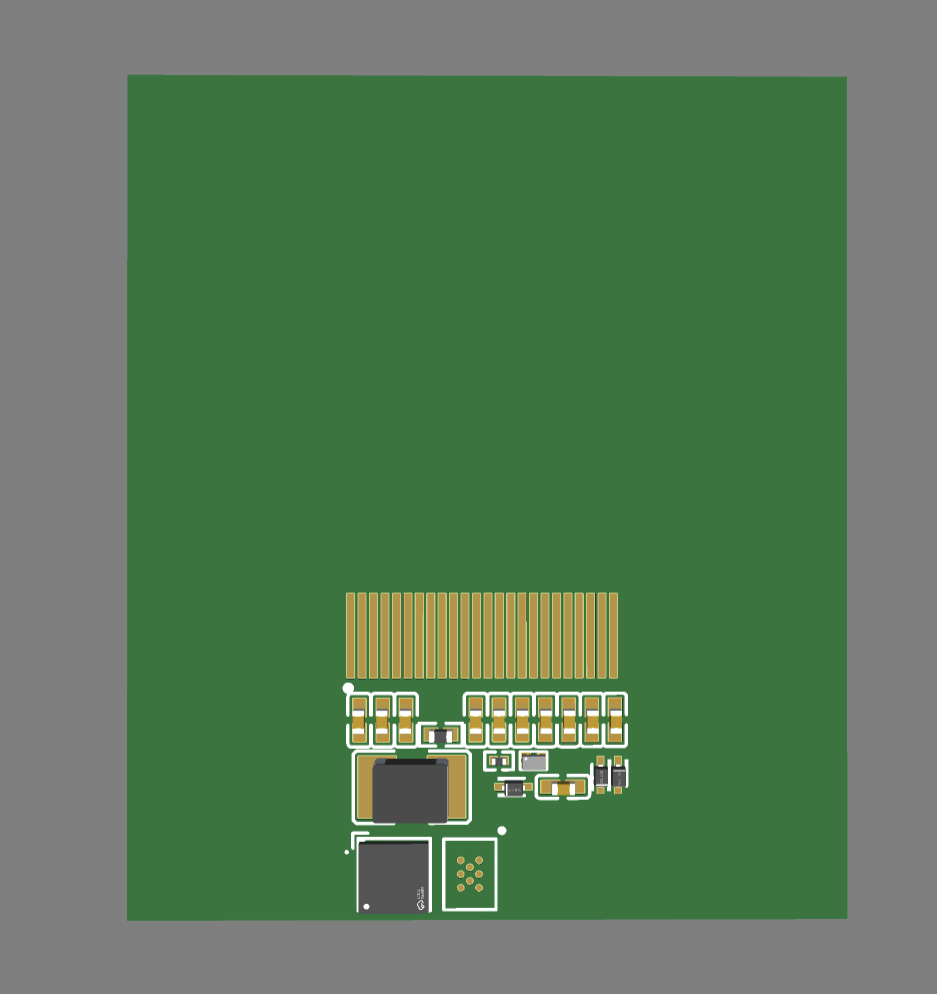
I decided to make a little mock-up of a possible flex PCB base for the 1.54 square flex e-paper.
All the passive components you see are required to operate the display.
Under the display you see one large chip and one unpopulated spot, these areas are for the microcontroller and the FeRAM storage module.
The most concerning part is the inductor, I asked the supplier if I could go with a lower current rating but they said it is not advised.
Please let me know what you think of the size of the area the passive components take up.

1 Like
Are those 0603 (1.5x0.75mm) passives or 0402 (1x0.5mm)?
I can review the design if you want.
1 Like
Everything is 0402 or smaller except for the active components. I tried to go 0201 on the capacitors as well but they had to be at least 25V rated.
What would this mean for the flexibility, is it better to place everything as close together as possible and make that area rigid or to have them equally spread over the PCB?
That is really appreciated, but this is just a simple ‘sketch’ to show the component sizes, so I’m not quite ready yet.
I should also switch to something more professional than EasyEDA software…
KiCAD is good, although a bit feature sparse. Personally I use Autodesk Eagle, although I try not to push people towards “the software I use” like most engineers.
I don’t know how familiar you are with ECAD, but I have a bunch of experience training people, so I could help with Eagle or KiCAD if you want.
2 Likes
I vouch for KiCad as well! Even a cracked Altium if you wear an eyepatch
3 Likes

Just a thought, could we use an xled as a backlight somehow?
Some updates:
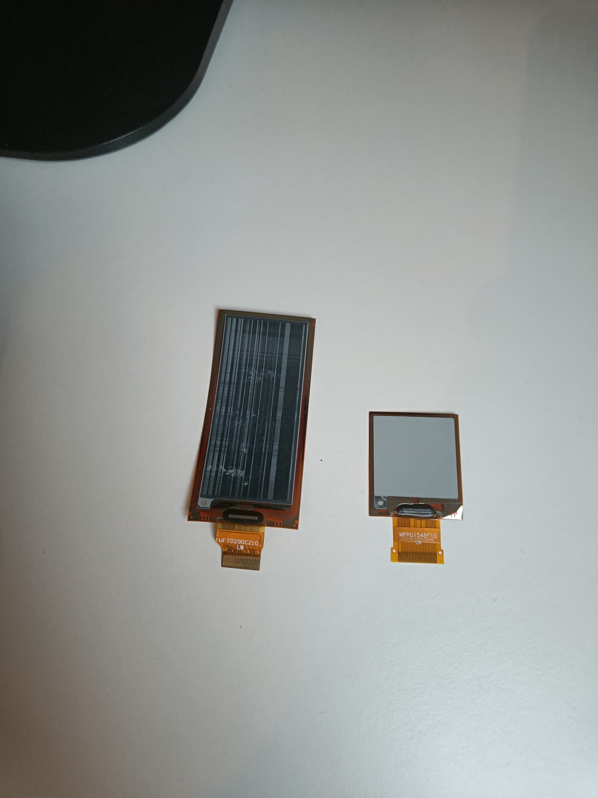
- The new display (152x152 flex) is almost on the way, this time I will do all the visibility tests before stress testing it.
- In the meantime I did some more researching and found a suitable ultra-tiny MCU for the job with all the requirered data transfer protocols.
- I’m still thinking about getting the flex colour display mentioned earlier to test, but since this one is significantly more expensive I would have to really think about it first.
- I was thinking that for large data transfers that are required to make this work it would make sense to include a red and green LED to indicate if it’s safe to remove the phone (so no data corruption occurs), let me know what you think about this.
My inspiration actually came from this video.
During programming (so with NFC source pressent), sure.
I do however think that it is very unlikely to make it light up all day long, this because you need a constant power source for that.
I don’t know about the safety concerns of implanting lithium-ion cells in a human, but I assume there are many.
1 Like
That makes sense.
But then I thought… wouldn’t “the image showing up” be a notification enough?
Or is it possible that the image shows up before you can remove the phone?
Exactly.
![]()
Hope that what I’m saying next will make sense to you and is not too technical/nerd-ish:
My idea is to make the memory chip writable through the NTAG I2C chip’s ‘pass-through’ mode.
This will use the internal unlimited write cycle SRAM, which the MCU will forward into the 1Mbit (128Kbyte) storage chip.
Because 128Kbyte is quite a lot to work with, I would like this to be user configurable (let the user say how much memory is for images and for their ‘secure data vault’)
The EEPROM (limited write cycles) of the chip would behave the same as the xSIID implant for smartphones.
If I’m correct it would be possible to write an app that can access the SRAM memory of the chip, enabling the user to flash new images.
Because of this behaviour like a normal storage device I would say that it is good practice to allow the user to know when all the data has successfully been stored.
2 Likes
Yeah, makes perfect sense.
I had thought of having it only “get an image from the phone. → display said image”.
If you have multiple uses for it, such as data storage, then something to tell you about the data transfer status would be great!
in which case an LED (you can do with only one. lights up while busy) is the most convenient option.
But what about… making the tattoo display a progress bar? ![]()
Nowhere near as optimal, and might sap too much energy.
But sure would look cooler!
2 Likes
Now that you mention it, the display has a feature called ‘partial updates’, which allow you to change a certain part of the display without drawing a new frame.
Feel like this would be an excellent application of this feature!
2 Likes
It’s been more than 2 weeks, time for an update:
I received the new display in the mail!
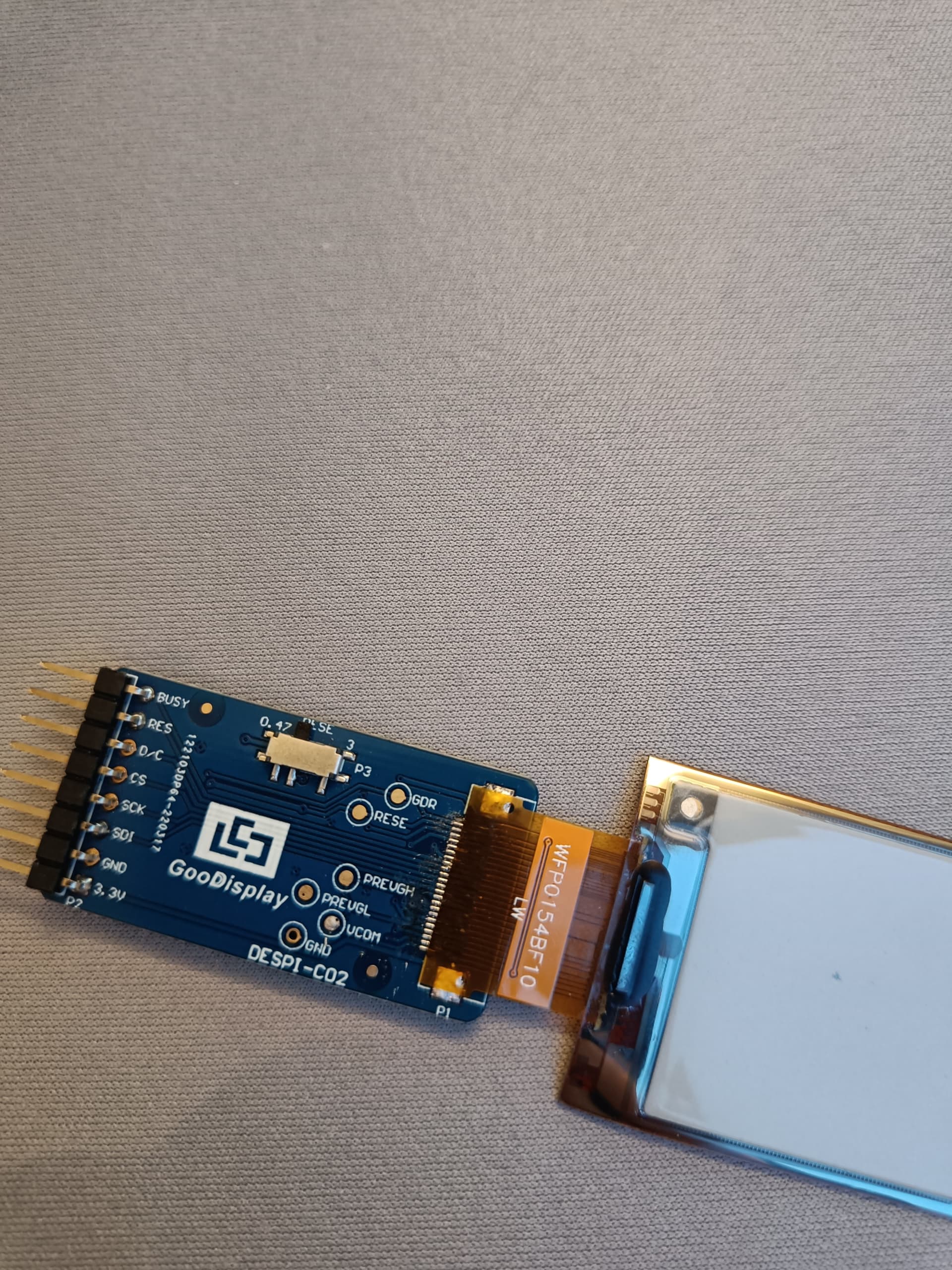
This display has a solder connector, so I will have to modify the prototype board, I will update you on how this goes.
The display seems stiffer than the larger one, this of course makes sense.
I still think the flex is enough for implantation, but I would need someone with experience to confirm this at some point.
I will be busy for the coming days, and I will share my progress here.
4 Likes
Quick update:
I did not succeed yet with using the display.
It’s probably the connector that is not soldered correctly.
I think I overestimated my soldering skills because I find it really hard to make all the connections (I’m already using solder paste).
If someone has suggestions on how to solder this display please let me know.
Edit:
Take a look at this solder connection, it looks pretty sharp to me but it isn’t working.
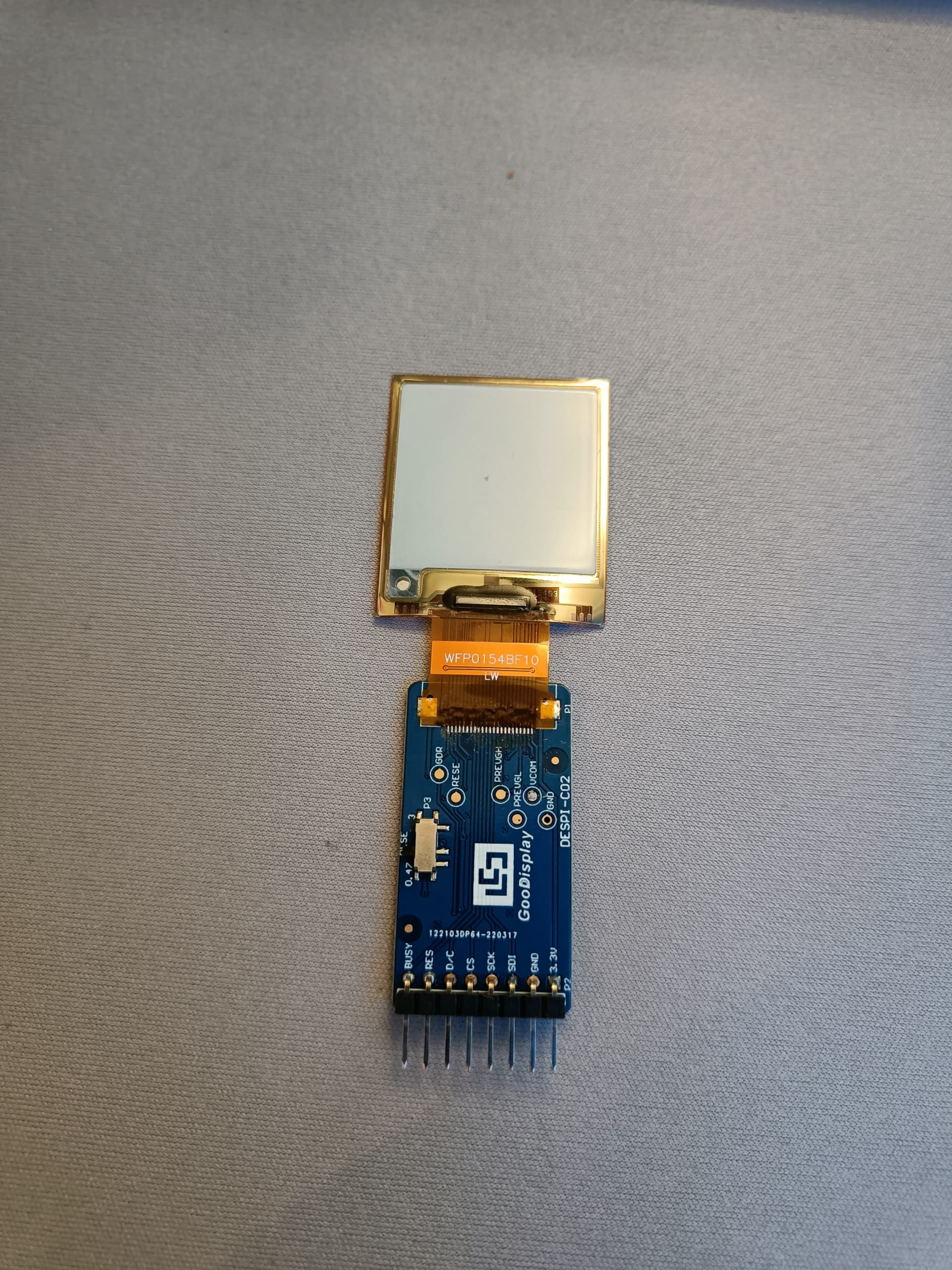
I can’t use a hot plate since the other side is also populated with parts.
Some kind of diy reflow maybe ?
I used a hot air gun in combination with solder paste because of the components on the back of the board.
Then I used heat resistant tape to place the display on the connector.
Not really sure how to continue from here, tried to redo it today but still no results.
You mean the paste doesn’t melt?
1 Like
It does, and it seems to make the connections as well.
The thing is that I can never verify this because the conducting parts of the connector are facing downwards.
1 Like
If you know or guess what resistance to expect between pairs you can check that. You can check continuity between neighboring ones to make sure there’s no short.
If you can access them somewhere else on the board that is…
Edit: also I haven’t really read the thread and reflow is not a thing I do often so I might be missing something. I’m catching up slowly!
1 Like
Flip it over and solder it. You can just run an iron down the length of the conductors. You’ll be able to visually verify if you have any shorts
2 Likes