Finally made my car implant compatible

I too bought an xEM controller for the same purpose, that I haven’t had time to do anything with yet. But I have a couple questions about the output signal you probably can answer then:

  • Do you drive the relay directly? How much current can you source? Is it 12V or something else?

  • How about timing? Does it send a pulse with a finite duration, or does the signal stay up as long as the chip is in front of the reader and go down when you remove it? If it’s the latter, is it “precise” - meaning does the signal go low predictably when you remove your hand?

The reason I’m asking is, I would like to use an xEM controller to start the car also, presenting my hand to the reader to power the starter motor, and removing my hand to stop it. But with older cars such as mine, you want to stop cranking as soon as the engine catches.

If the xEM controller’s signal goes low as soon as I remove my hand, I can use it to control the starter motor directly. Otherwise, if it stays up for, say, more than half a second after I remove my hand, I’ll have to install a separate button to crank the engine.

I used a common automotive 12v relay, I am driving it directly and the xEM has no trouble with it.

Basically the signal wire only goes high as lo g as the led is lit, aka as long as a valid card is held.

The power cut off is instant, as far as human noticeable it is. So for starting a car I don’t think it should be an issue.

If it is you could probably buy a push start conversion kit and wire the xem to activate it.

Yes it does, I can vouch for that, below is a video link of Amal using his on a demo setup so you can see for yourself.
Also You can do a quick and basic bench setup to test yourself

The xAC operates between 9V-15V, but I am not sure about the current rating ( From memory it is not particularly “high”.)
Fine for “Low” current projects, But I would reccomend putting a Diode on your White wire, and switching an Automotive relay to your starter motor…

Just saw @ChildApple reply above. AGREED

1 Like

Great! That’ll make things a lot simpler and smarter-looking too.

Doubtful, on a 13 year old el-cheapo Fiat panel van :slight_smile:

1 Like

You will actually find it easier. No Immobiliser, nor ignition / key chip…
Personally I would go for a Push to start like @ChildApple suggested over going direct to the starter motor.

Something like THIS will do you nicely

3 Likes

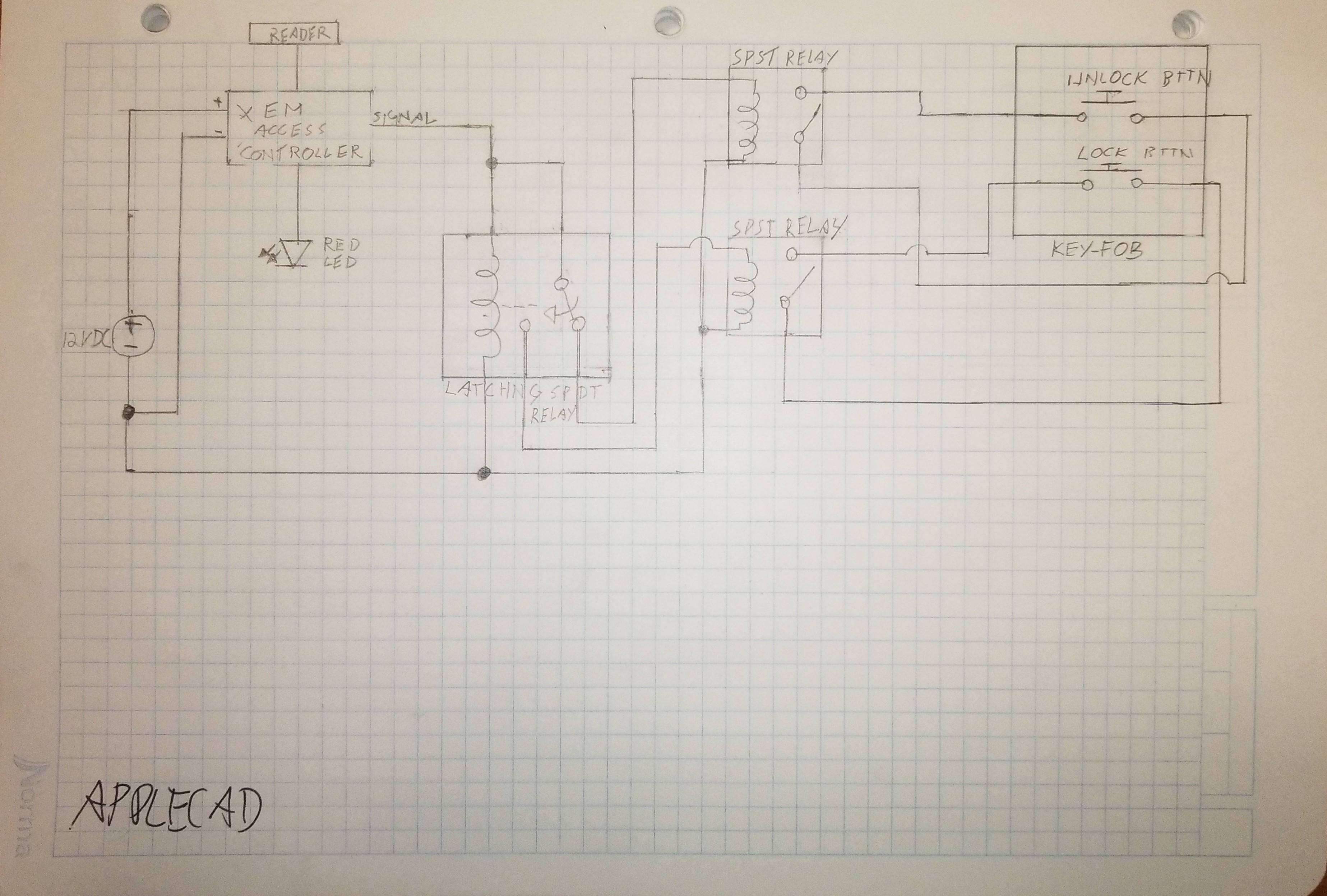
Do you think this would work to switch between “pushing” the locked and unlocked buttons?
I don’t think it would be a problem for the xEM to actuate 2 relays?

All I’m worried is that in this configuration, the latching SPDT relay will power actuate one button before switching and then activating the other one. Maybe that could be an issue?
Maybe something can be done to prevent that?


Thx

2 Likes

You wish… The damn thing has an immobilizer that uses a 433 MHz ID46 transponder in the key fob.

I’ll have to remove the ignition key lock tumbler/cylinder and switch (probably get a garage to do that bit, since it takes some heavy drilling), saw off the steering column lock, solder wires to the ignition switch, put everything back together and duct-tape my spare key in front of the antenna inside the steering column.

And even then, I’m not sure it won’t trip the computer: from what I could read, some cars expect the chip to “come into view” of the antenna only when the key is turned. When those computers read the chip with the key in the off position, they disable the engine.

An easier solution would be to leave the key in the car at all times, and simply disable the ignition with the xEM. That’s one way to go keyless with RFID and have a separate ignition switch :slight_smile: The trouble with that is, it’s an open invitation for car thieves to break the window in the hope of an easy steal.

1 Like

Yes that would work, if you looked at switching up the circuit to use transistors and optocoplers you could do it small enough to fit inside the xAC. But in principle nothing wrong with your circuit.

1 Like

APPLE-CAD :laughing: Is that freeware? looks pretty well spec’d
.
Circuit diagram looks good to me.

With your Double throw relay ( you probably already thought of it, sorry if I missed it in your diagram ), I would suggest the normally Open is your lock state, so when Unlocked, your car will likely be driven- and alternator charging battery, and when locked, no current draw.

Good question, at first I thought :bulb: there was no issue, but you made me think :bulb:
about it…I think :bulb: I know where you are coming from. I think :bulb: it will be fine…I think :bulb:

1 Like

That would be my first test

  1. Remove transponder from your key,
  2. leave the transponder in the car right by the ignition.( around the ignition barrel )
  3. Lock the car
  4. Wait a period of time
  5. Unlock the car
  6. Start the car ( With the transponder still in place )
  7. If it works, you should be golden!

Obviously I’m not familiar with your car, but the handful I have dealt with, your process sounds more extreme than I would have thought necessary.
Remove the steering boss/shroud
You should find somewhere on the barrel housing a small metal detent
Use a screwdriver or similar to depress the detent at the same time
insert the key and turn it to ACC or on.
The detent should “give” and you will be able to remove the lock barrel.
TA DA :mage:

Around your lock barrel shroud you should see the immobiliser antenna, which is where, IF your transponder test from above worked, you will hot glue / tape your transponder in place.

The hole where your key barrel was, Is now where you can mount your Push to start button.

HOPEFULLY, this process makes sense and more importantly it works for YOUR current setup.

If not, let us know how your testing goes, and maybe start your own thread in the projects section, talk us through your findings, and hopefully through the community somebody will be able to help.

1 Like

So in the diagram I’m planning on powering both the latching spdt relay and the spst relays all 3 with the signal line of the xEM access controller (xEMac) , that way when the xEMac signal line goes low and stops sending 12v+ then all relays are unpowered. Therefore the only device drawing power is the xEMac.

Or should I maybe not drive all relays with the signal line?

2 Likes

No, right you are, Good catch…Relays only energised when your xEM/NExT is presented.
Therefore your only current draw should be your xAC of around 11mA
:+1:

1 Like

Hey do you mind explaining like I’m 5 how to use transistors and optocouplers for this?

Must have spent couple hours reading stuff about how they work and what not over at sparkfun.com but still don’t understand how I could make a latching relay with them.

Also how would I wire the thing together?
I assume some wizardry with the transistors to make a latching switch, and then the optocouplers for actuating the keyfob? But they seem complicated needing to add resistors and capacitors and what not apparently…

Thx for any help. I think it’d be best to fit everything inside the xEM access controller, but if I can’t figure this out I’ll just use big clunky relays.

2 Likes

I will do after work, I’ll use this as a place holder till then.

EDIT 1:
I havent forgot this, I will be ordering an xAC tomorrow I’ve prototyped a circuit that appears to work. I’m also gonna design a little PCB as an add in for this purpose. It will be completely open so anyone can order pcbs for any supplier as long as there competent at soldering.

3 Likes

Right this is the circuit, it works in principle I’ve driven LED’s on the outputs and the blink very quickly (may be too quickly).

Hopefully the circuit makes sense any questions I will do my best to answer.

1 Like

I see you too, are a proponent of AppleCAD™ :wink:

I might have to add your plans to my project to do list…

I hope it works well for you @ChildApple

1 Like

Can’t beat a quick sketch.

Any who I’ve gone and done a board, I’ve kept it as small as I can without making the soldering too difficult. Board measures 25 x 28 mm, I’m going to order a handful once they arrive I’ll put them together an we will see what happens.

P.s. at this size more than capable of fitting inside the xAC.

P.s.s. believe the board can pick up 5v from the xAC controller board but am unsure on current consumption (how much over head is available in the controller) worst case a 7805 tacked inside will do the trick.

3 Likes

Love your work mate.
Great stuff.

1 Like

Same deal here. I have a Crown Vic. No immobilizer, no chipped key. I eventually want to make it chip based but I don’t have the time and I also need to fix the car up before I do that.

3 Likes

Wow, this is so much better than I had any right to expect.

Kinda understood most of it, now to find the correct components lol. Like no clue what IC5 is or does. nor where to source them

Are you planning on building the actual board? Who will you have them print it?

My soldering skills are meh but i think I could get the board together.

If you some made I’d love to buy one from you.

Maybe you could have a market here if you sold the boards, make it way earier for people to wire up their cars with an xem and a key fob.

Anyway thanks!

2 Likes