Hey all you Blinky Boys ( and girls) with a Flipper and penchant for RGB Blinky
I did a Flipper RGB Mod
This is not my original project, smarter people than me came up with this, I’m just the monkey on the tools in this instance
I have provided links below to guides rather than writing it up myself, so let’s call this a Project LITE
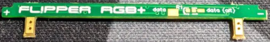
I got a Flipper Zero RGB PCB From @Hamspiced
He sells them on Tindie, But i’m not sure how much Tindie clips the ticket maybe contact him on the forum to support him directly ( I’ll edit this sentence when I hear from him )
There are a few guides online, here are a couple
FOR THE READERS AMONGST YOU
FOR THE VIDEO WATCHERS

I watched the video, this one was edited from a live stream, so the edit cuts out a couple of bits like the disassembly tabs and screw locations, but they are easy enough to work out.
It’s a bit rambly, but still thankful to “the Talking Sasquatch” recording , editing and sharing
A couple of key notes and differences
Get your tools ready
- Small long neck screwdriver
- Spudger tool
- Thin wire (about 100mm will be plenty)
- Soldering iron and solder
- Flux (useful but not necessary)
- Solder sucker (useful but not necessary)
Be careful with the pogo pins ( for the iButton )
Take note of which screws go where
@Hamspiced RGB Module is different from the one shown in the video, In my opinion better, his board has the pad in the “centre” rather that of the edge which allows the bridging wire to run / hide behind the screen ribbon cable.
It is mentioned in the video, But I also recommend soldering to GPIO ground instead of the ground pads suggested in other guides
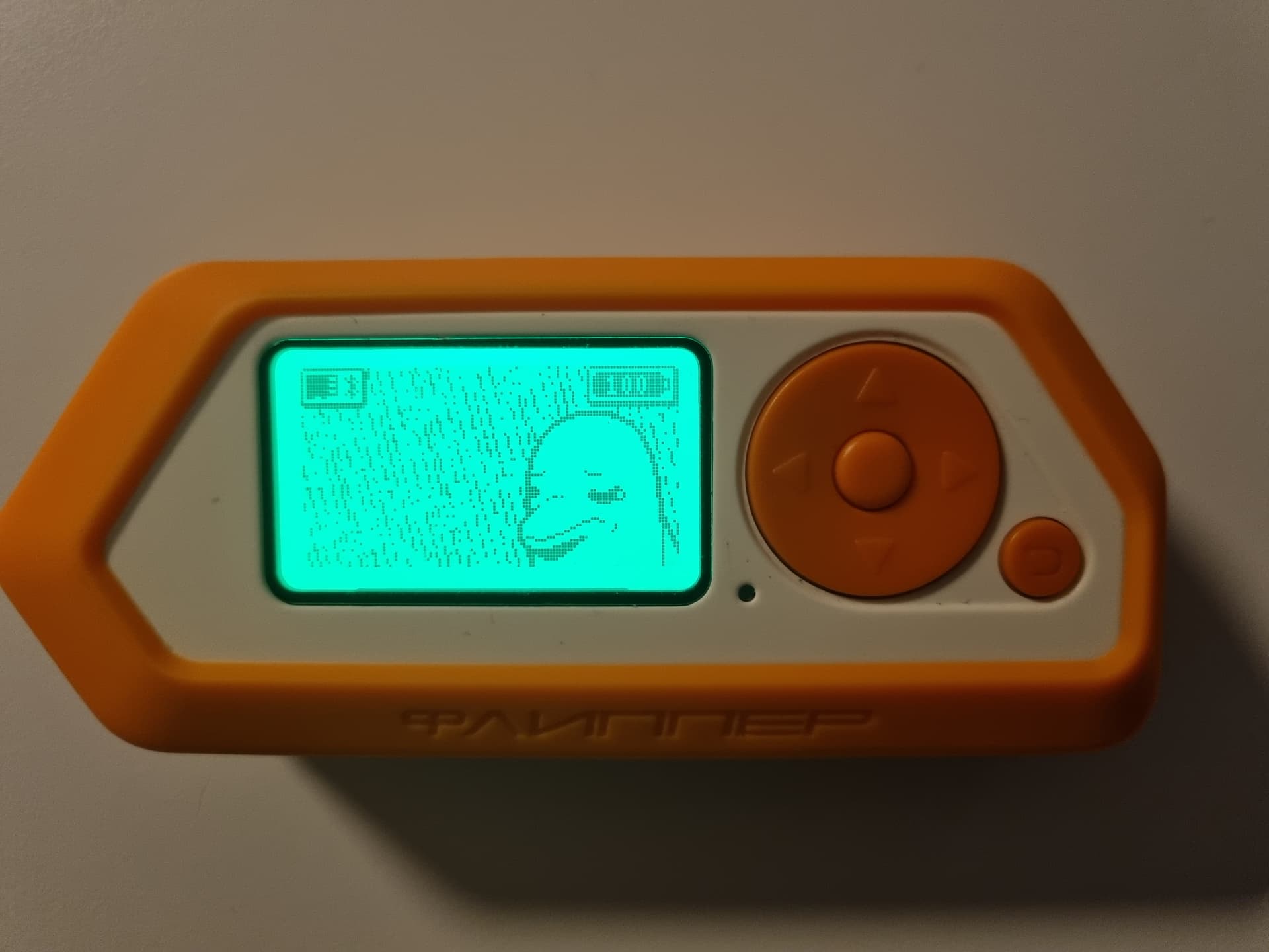
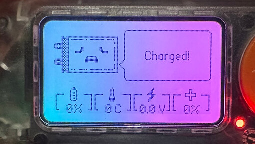
After following the guide, you may see there is no LED backlight.
Also, you might need to reboot the flipper.
To get your BLINKY Fix
![]()
![]()
![]()
![]()
![]()
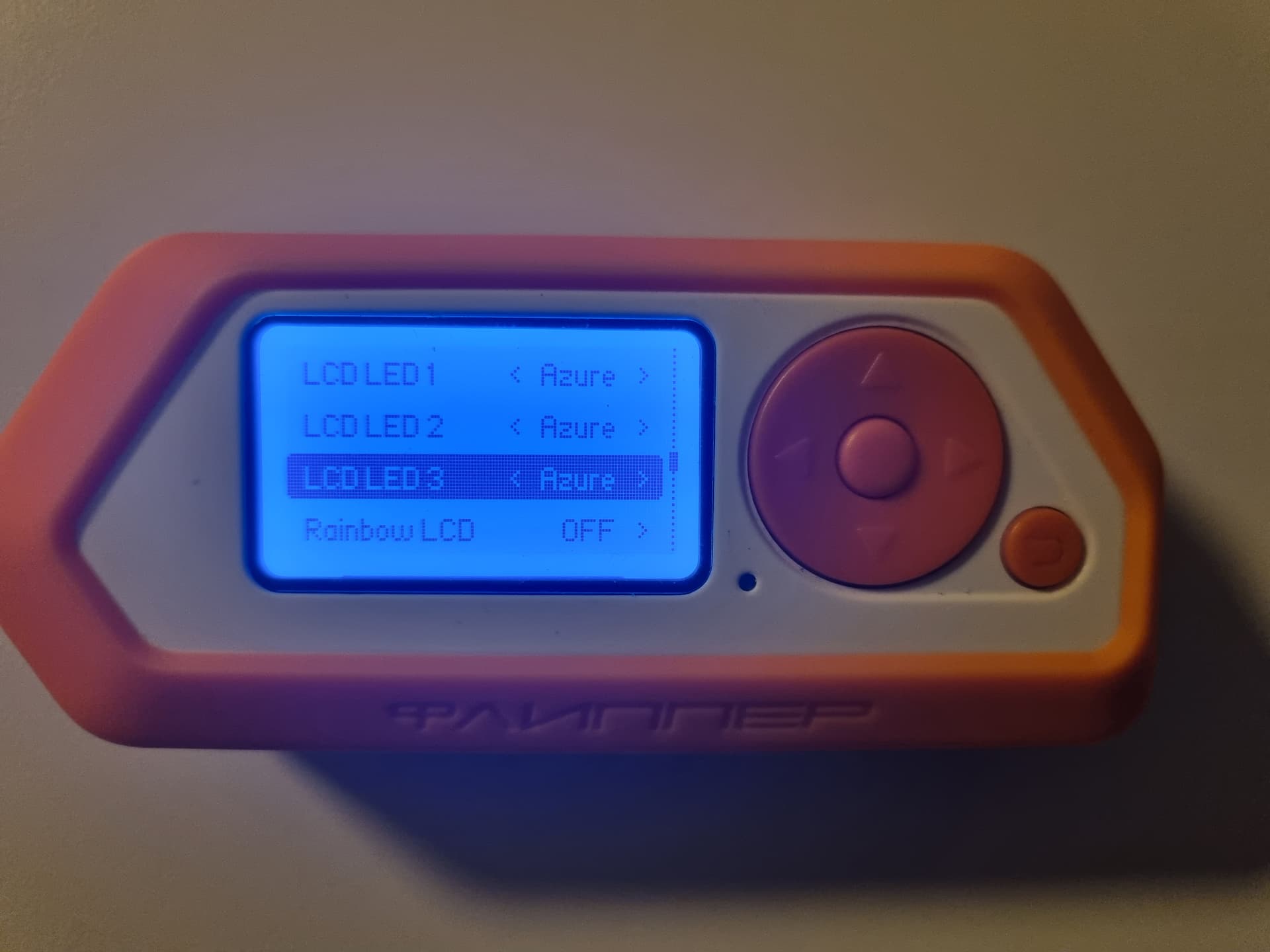
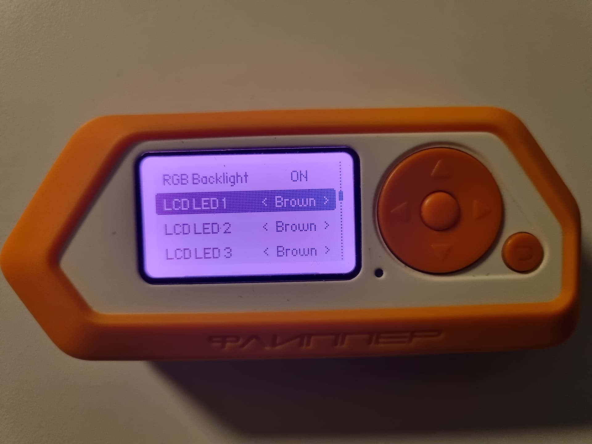
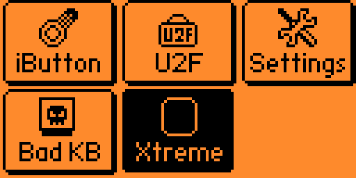
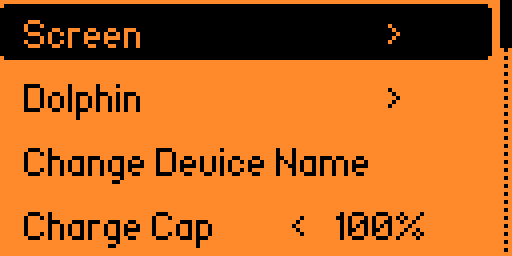
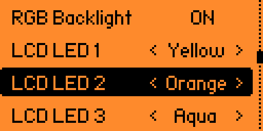
Set Up RGB in your Flipper
Here’s how in Xtreme firmware
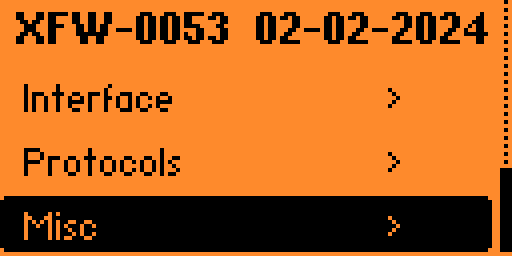
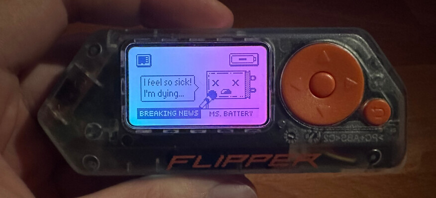
If you want to taste the rainbow ![]()
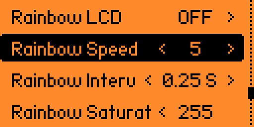
Then you’ll get something that looks like this