I’m changing your brightness does it affect the LEDs?
I accidentally read the title of this thread as “Finger RGB mod” and now want more implants…
2 Likes
I was just about to suggest what @Hamspiced said, I think I see where he is going with that…
do all 3 leds change?
Have you tried all the way bright?
Have you tried all the way dim?
Spicey Hams boards have an optional resistor pad, which I didn’t need to use, neither did the spice miester, but you might need one?
Alternatively, try an alternative pickup to the VIBRO, the alternative might work without a resistor ![]()
Do you have a spec sheet on your LEDs?
LED brightness setting - no, LCD brightness setting - yes
Not looking optimistic. I’m starting to think I inadvertently cooked something on the board while I was soldering ![]()
I checked with a multimeter and the battery is still running ~4v which should be fine.
I’ll see if I can borrow another flipper and swap batteries to get more information this week.
My board had a trio of capacitor pads, but no resistor pads.
He has the v1 of these I believe. Not the new complete board . His boards have 3 resistors
I think I’m your soldering you may have one led ran to ground and it’s causing your issues. If you can change the color through the brightness then that may confirm it
1 Like
They’re just some generic 1515 SK6805s that I picked up on aliexpress but they’re working great.
I just did the RGB mod and am having a similar issue. No matter what firmware I use it doesn’t have the RBG settings and I don’t get any backlight at all. I haven’t tried stock firmware and the upgrade but it sounds like you did and it didn’t work.
You have to use the RGB Variant of Firmware. Unleashed has it designated as an appending r. Ie this firmware link should have it.
i also forgot since it has been a while since i did mine. you have to run a line from VIBRO to data on the back, and then a jumper for ground. As long as those two lines are ran and this firmware is installed it should work fine.
You’ll have to run the extra wires detailed by hamspiced, the LEDs aren’t going to light with power only like the old orange LEDs.
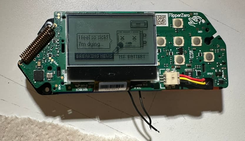
My issue is with the battery percentage not showing. I got a friend’s flipper to compare boards to and they look identical so I’m losing hope in that regard. The RGB LEDs work fine on Xtreme.
I have tried xtreme firmware and momentum. The RBG Backlight options are missing in the momentum menu and I have no backlight at all. In xtreme I can turn on RGB mode but still no backlight. I did connect to a GPIO ground. I did try the two little pads first before someone reading the GPIO ground and I moved it there thinking that was the issue. I’ve unplugged the battery and rebooted. Everything seems to be working, other than backlight.
It should be in the Xtreme app → Misc → Screen and then you should see RGB in the list to enable, then it should come to life. I don’t have my flipper right now (my brother has it) to show you but I guarantee, at least on the release I have (XFW-0053_02022024), it works great.
1 Like
Xtreme has the settings but when I turn it on no LEDs come on.
Edit: I have this board - https://www.tindie.com/products/hamspiced/flipper-zero-rgb-mod/
and I wired it up as suggested in the video. https://www.youtube.com/watch?v=5zaDRNvif9M&t=827s
Other than I went to the GPIO ground vs the 2 little pads.
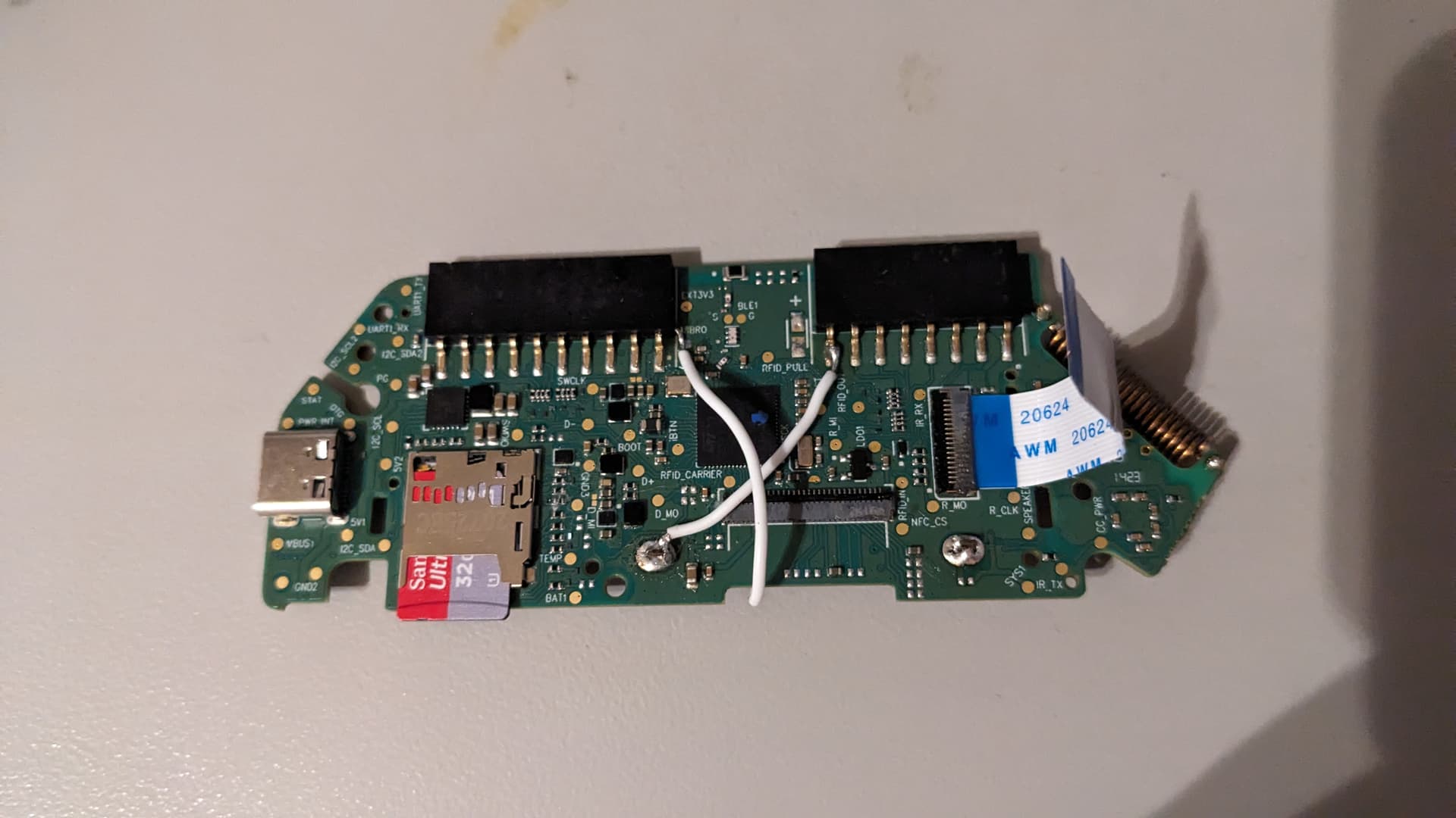
Can you take a picture of your PCB if it is accessable?
1 Like
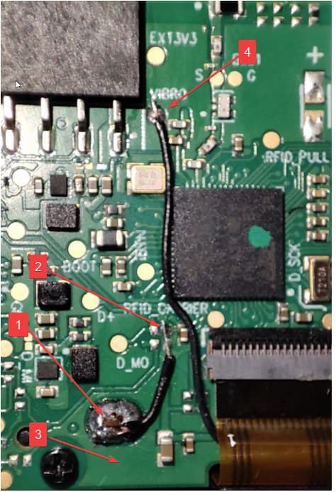
You have two jumper wires that will need to be added.
One will jump off of the RGB board and to a pad above the rgb board see Diagram item 1 and 2
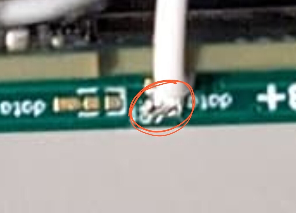
Another will go from the pad labeled VIBRO to the RGB Board (see item labled 4 on diagram). If you use one of my White RGB Boards it is to a pad labled DATA. If you use one of the first gen green boards it will be to the far far left leg of the RGB board.
1 Like
Thats how I did mine also
I think Hammy is on Unleashed, im on Xtreme
Both of ours work.
The Xtreme FW I show the steps in my first post, have you tried that?
Also, did you do continuity tests as you went?
The posts from the RGB Board, did they get a good resolder?
I just checked your photo, They lok like they should be OK.
It probably wont hurt to build the volcano to make sure you have good connectivity
Did you “clean” the pads afterward, ie. check there are no shorts
This ![]()
Ahh, you’ve done it, Im still reading through
Your GPIO Ground looks good, The RGB leg looks OK
I would like to see the Data Pad a little clearer and also a tighter clearer shot of the VIBRO
You may have some errant strands of wire causing a short
Infact, can you do a close up of all of them.
Do you have a multimeter?
@Hamspiced
Your thoughts?
1 Like
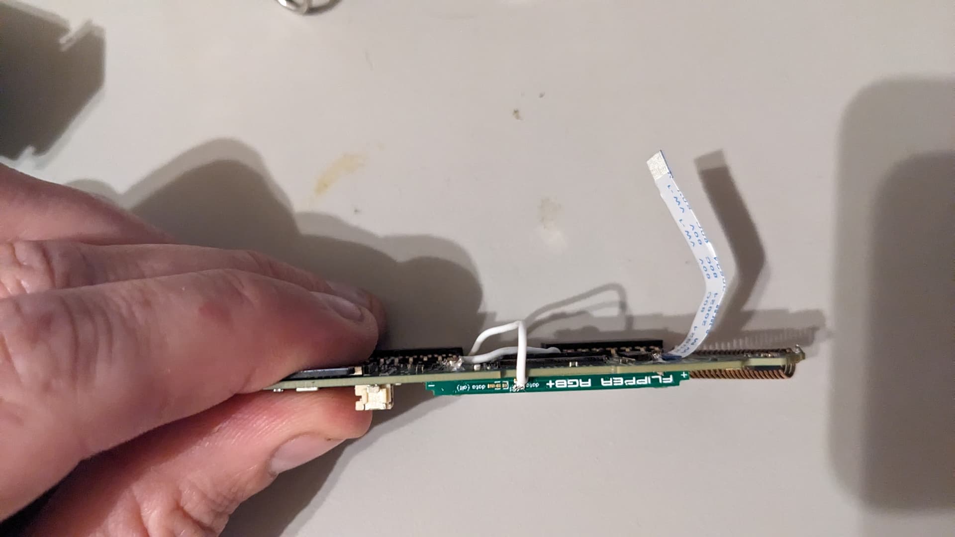
Can you take a picture of the other side of the board as it rests on the reflector?
There are two versions of the flipper. They outsourced suppliers for led and reflector and they have two different types. Your original box will denote this as RO1 and RO2.
The RO2 needs to have the reflector carved out to accept the cap that is on the board. If it isn’t carved out you’ll rip that cap off forcing it onto the reflector
1 Like
Probably the cleanest hand solder job I’ve seen in a while. I’m guessing a capacitor was ripped off when sliding it into the reflector or the firmware wasn’t picking up the board. My only two guesses but I don’t think it’s related to the solder job
1 Like
That does sound more feasibile…
Yeah, it was a stab in the dark…my guess that is not the solder.
I would have liked to seen the soldered ends a little tighter
@aw9d, not shitting on your work, there were a couple of things for me
I would definately like to see a close up of this
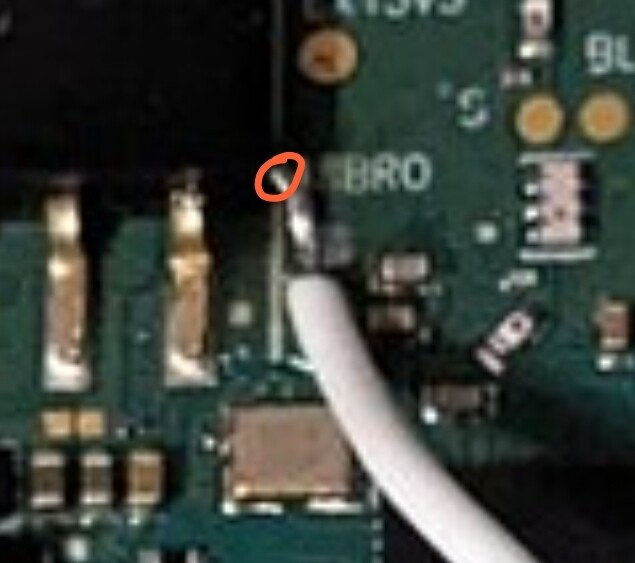
This one I would trim the end, but in saying that, I think it is far enough away from anything of concern.
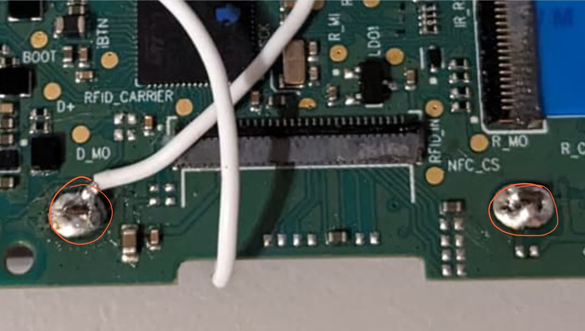
I went heavier on the solder of these to ensure good conection with the RGB terminal pads
I also went for a finer gauge wire, but that was so I could get it back together easier and not fight the tight tolerances.
Just my thoughts, but Hammy is probably correct
1 Like
So I’ve only heard of this one other time where someone wired up their board and it never lit. So they ran a jumper from the right rgb board leg to the 3v3 pad above vibro.
https://www.reddit.com/r/flipperzero/s/OJtG0NNlF6
I didn’t recommend this at all. He’s bridging the two optional pads that is for an additional resistor that isn’t needed and I’m fairly certain this will cause the display light to never time out. No clue though because he never responded
Here’s what I would do. I tried to not piggy back off of gpio. I recommend the same and run your jumper to the small pads like the attached image. The only other thing I could think of is your wire gauge is too thick.
Honestly I think the capacitor was ripped off or the firmware didn’t install correctly. That’s my only two guesses.
Note that the presence of the board does not create the availability of these features so I’m unsure if the momentum branch has the patch added.
I do remember though that I had to increase my brightness after I enabled RGB in my firmware as brightness was set to zero. I don’t know if Xtreme is the same way. Maybe @Pilgrimsmaster you remember?
This only jarred my memory because after I powered it on I had no backlight and I thought I messed it up.
1 Like