Mine was set to default and worked straightaway, I don’t know if that was a me thing or xtreme thing
1 Like
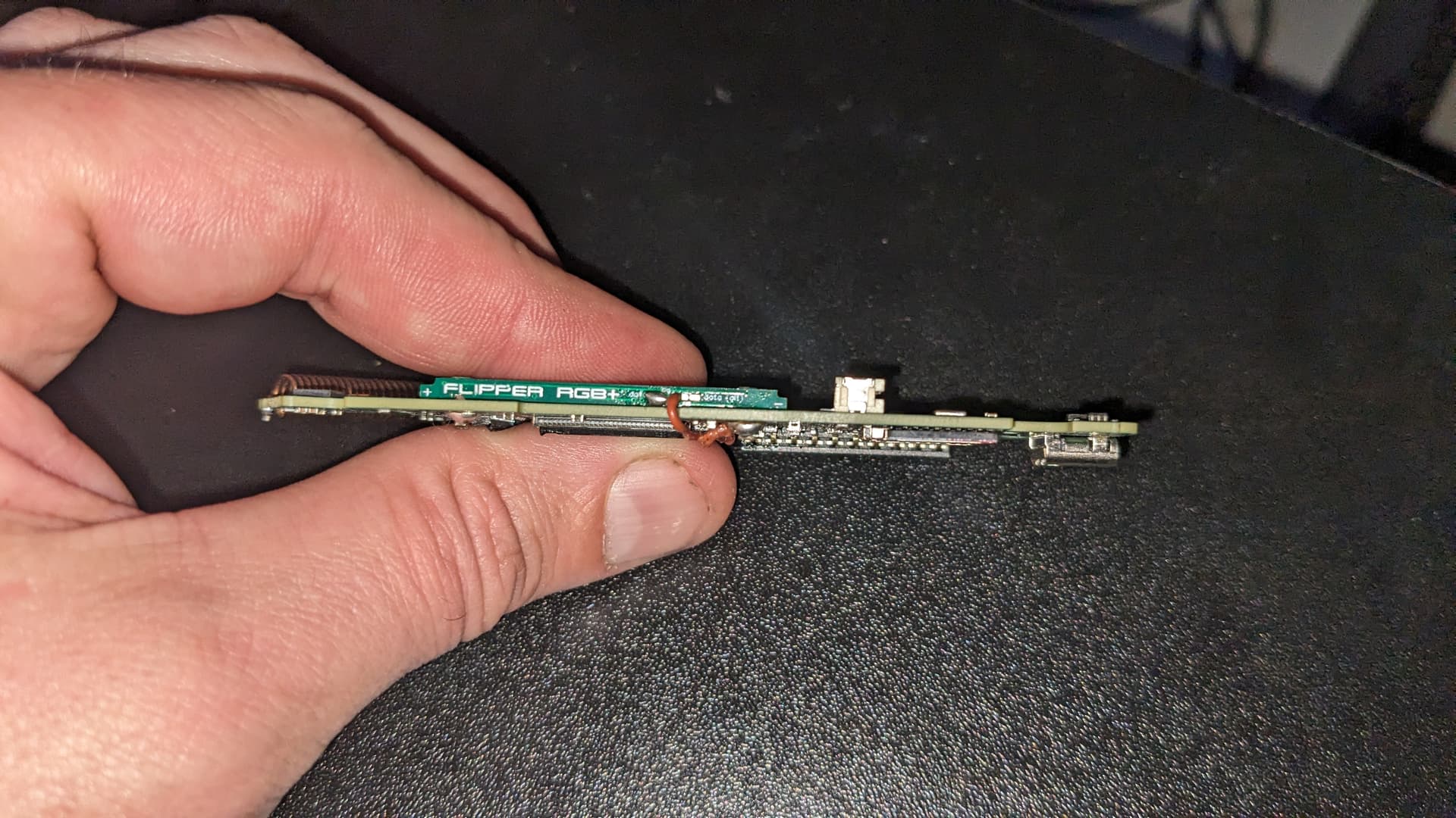
Feel free to shit on my work! It’s been a loooong time since I worked on something this small.
I used to do work like this in my 20’s. Now in my late 40’s I figured I’d give it a shot but my vision sucks now. I’m using a magnifying glass when trying to do the work. I need something better to see this small.
As for cleaning I did clean up everything with rubbing alcohol and a q-tip after doing the work.
I do have a DMM I can test with.
I appericate all the help everyone. I’ll go clean up what was suggested on my lunch break.


2 Likes
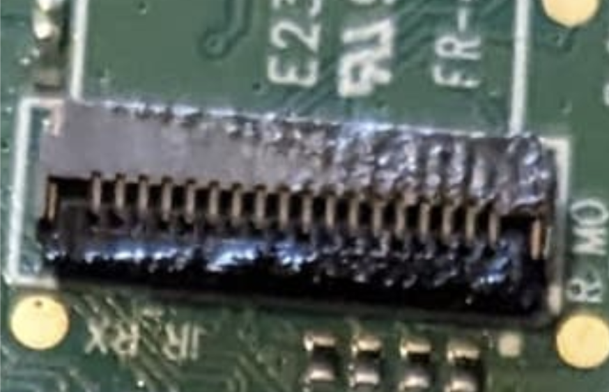
Okay i think the capacitors look good.
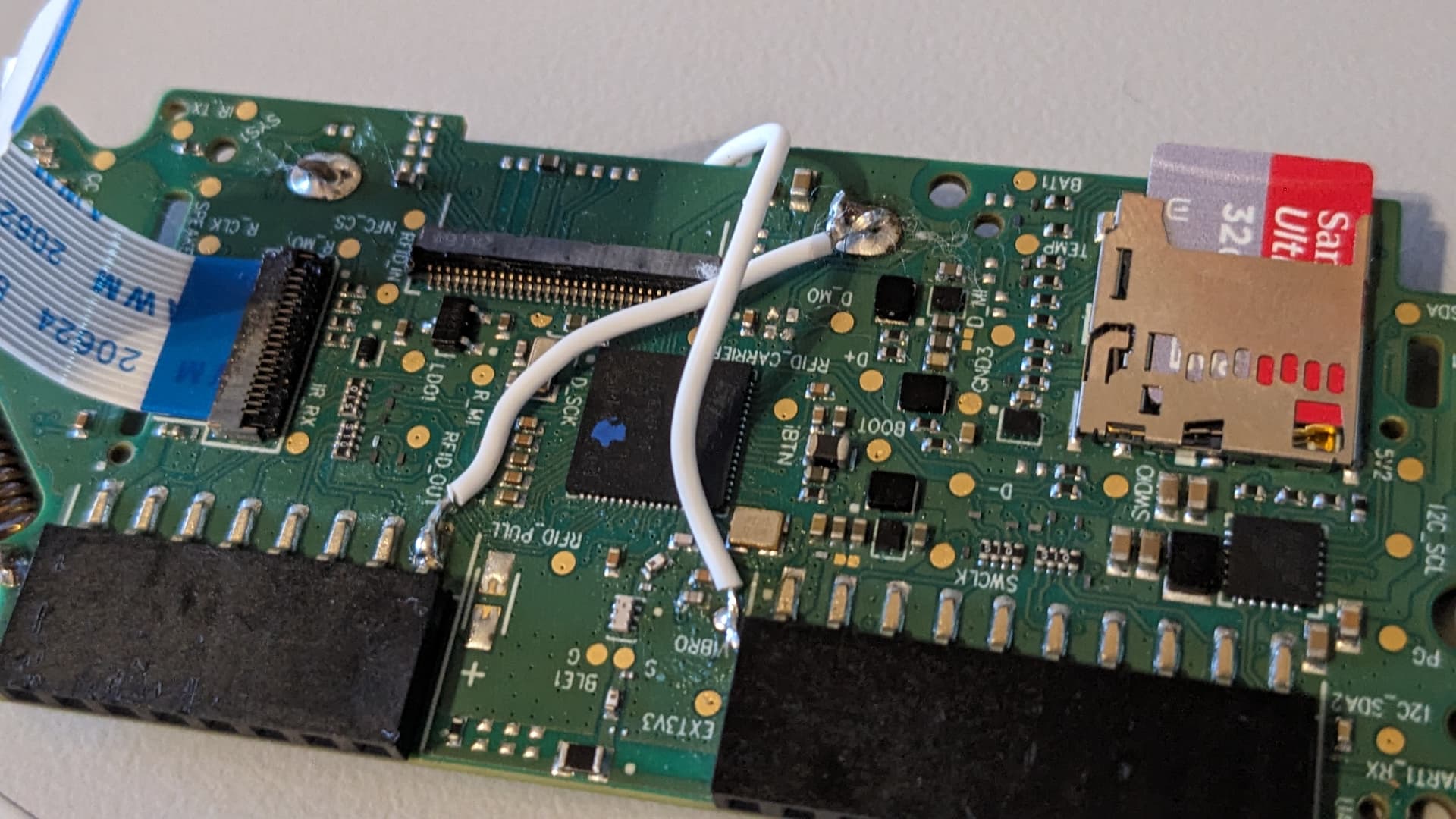
next, that wire is thick. like 4x the thickness i used on mine. I cant imagine that caused your issue but i would consider replacing with a thinner guage. i actually used cat-5 stranded wire for mine.
next. the wire that runs from the RGB board to the gpio pin is your ground. I would consider running the ground to the ground pins above the post.
Last. the other post is your positive. Maybe reflow that area to ensure it makes good contact to the board.
Your vibro pad while it does look like it is connected, it should probably be adjusted to be a bit closer to the board.
This aside everything looks good. Just be careful, these boards lift pads pretty easily if you get them too hot.
2 Likes
Thank you for the feedback. I really do appericate it.
I’ll clean up the vibro and reflow the positive.
When you say “I would consider running the ground to the ground pins above the post”. Can you elaborate?

Thanks for the reply. I was hoping that wasn’t what you were referring too ![]()
I didn’t have a chance yesterday to tackle this. I’ll try again today if work allows me too.
Again, thank you for the help!
I think it’s more to do with the wire guage than your work itself.
That was my plan also, but I had some .28mm (36AWG) wire handy and used that.
My Mrs can’t say the same about me
Whatever works.
Let’s wait until after the reflows, rewire and relocate or whatever you try next if you have no luck
Just waiting on these to show up tomorrow and hopefully I can tackle this again.
I have some Cat5e laying around I can chop up for the wires. I ordered one board on tindy where the data connection was on the side and didn’t like the way it was fitting. They gave me the wire so figured I’d use that. But the Cat wire idea is great!
1 Like
no shame man, i use a Jewlers Loupe all the tie.
The boards astro sells look like they are pretty good. The other basic boards i used to sell until the new revision.
lmk how it goes.
I use single strands from Cat5 all the time. its great for little projects.
1 Like
Me too, they are REALLY good and under-rated.
Great for pushing through holes, rather than the multi-strand which is like pushing rope
4 Likes
So while I’m waiting for my eyes to show up. I just have a basic question.
Why is it better to ground to the two pads vs going to GPIO ground pin? Just curious.
I’ve seen two cases where it was an issue for different reasons.
One involved using certain devices on the GPIO and it caused issues with the device. IDK if it was causing an increased draw or not.
The other issue is the one posted above where the guy had to run a separate 3v3
I personally grounded to the 2 pads above the ground leg and didnt have any issues.
Interesting. Thanks for sharing. Now that you told me about the Cat5 wires that should really help getting to those two little pads.
Heres how i did it.
I cleaned my tip really well. Then a tiny dot of flux on the two pads applied with a sewing needle. Lightly tin the tip and tap the tip to the 2 pads and it just sucked the tin up from the tip.
Next, tin your cat5. place it on the pad, and touch the wire to the pad. then i stripped and cut to length to the ground pad of the board and solderd as normal.
Also used my jewelers loupe the whole time.
2 Likes
Well I tired again and had better luck with my new set of eyes. Still no go… I really wish I never started this. I just hate the color orange. So frustrated.

1 Like
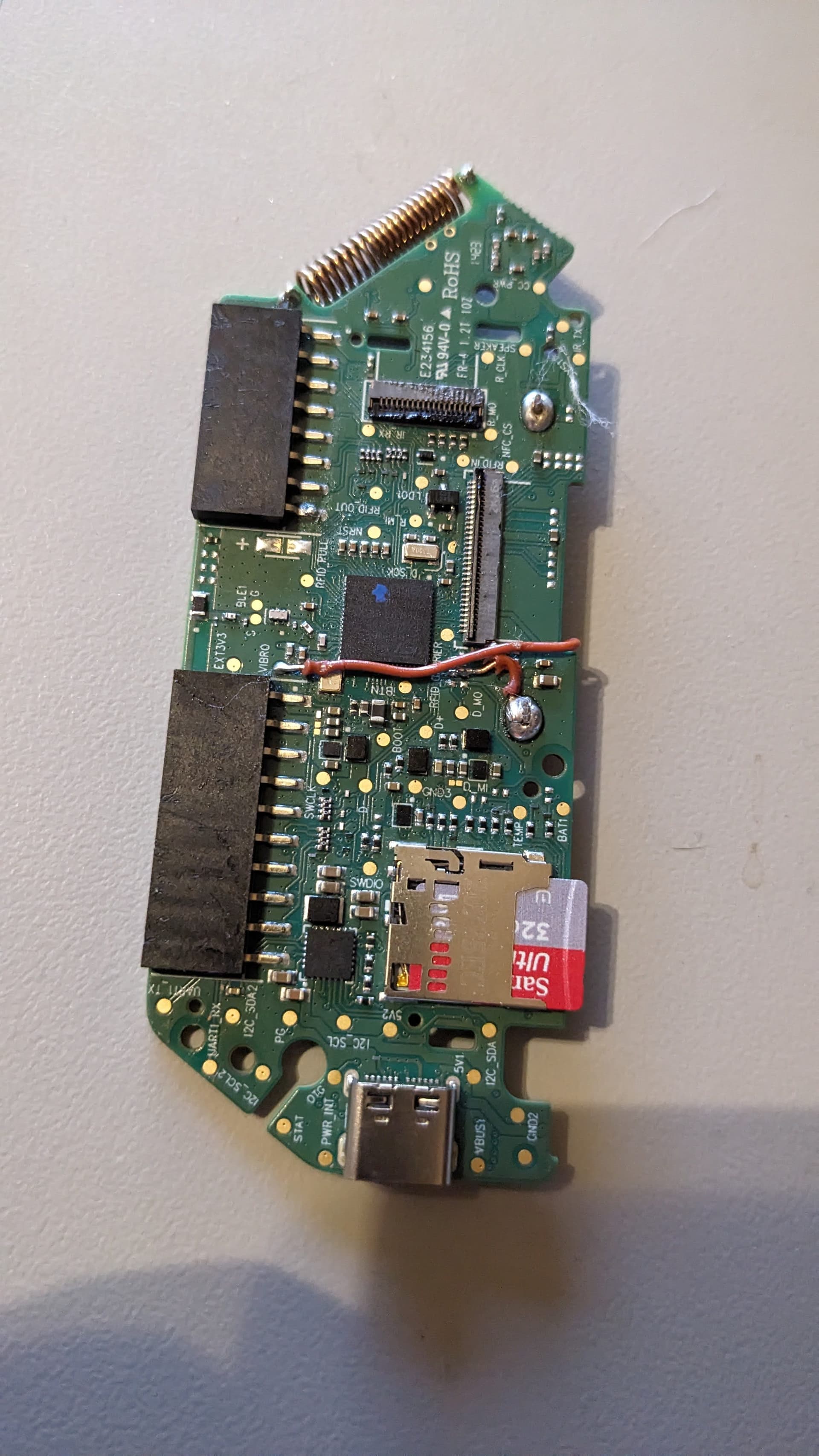
Everything looks great. Honestly. What firmware are you flashing with?
Xtreme’s latest: Firmware:
XFW-0053 02-02-2024
I’ve also tried Momentum v1.
Well momentum doesn’t have the RGB patch installed.
Do you use qflipper to install the firmware or the Web updater?
Once powered on go to Xtreme>misc>screen and turn RGB backlight on.
Screenshot is from @Pilgrimsmaster install log.
I’m really hoping it just has to be enabled.
If not I can offer you two solutions. One I send you a new board and I’ll cover shipping and the board. Two you send me the board and I’ll fiddle with it with my own set of bad eyes
1 Like