Frankenstein the xEM access controller for proxmark proxlf

Hey all,

I’ve seen some very smart people engineering creative LF antennas for the proxmark. Though I hate to potentially sacrifice working gear (though it should be presumably reversible) could we not “borrow” the LF antenna from the xEM access controller?

I’m suggesting this because I believe the built for purpose LF implant antenna is out of stock no?

What are people’s thoughts :slight_smile:

Yes, but no.

It might work, but it very much depends on your exact proxmark. The tuning is a product of the antenna’s inductance and the capacitances on the circuit board.

The tuned antenna that works really well on an access controller could be so far out of tune on your proxmark as to be useless.

On the Proxmark RDV4, the tuning caps are on the antenna board, so as to make it a plug and play solution with the ProxLF. If you have an RDV4, you’ll need to figure out what supporting capacitors you would need to tune it.

All other proxmarks, the caps are soldered to the PCB, not the antenna. Basically, the antenna has to match whatever was supplied on your board.

Some people have done it before, with mixed success - I ended up just winding my own antenna though.

1 Like

Thanks for the detail, I’m still in the market for my RDV4 so not a problem I’m facing yet :slight_smile:

Really good question, This thread will be absolutely right up your alley.
For reference, TomHarkness is the designer behind the PM3 RDV4 antenna.

1 Like

Thanks so much @Pilgrimsmaster <3

1 Like

The OP in this thread tried it :slight_smile:

2 Likes

nice - lots of knowledge to be shared then!

1 Like

We’ve got a whole collection here if you are

https://cyborg.ksecsolutions.com/product-category/rfid-tools/proxmark-kit-addons/

There’s also loads of setup guides and how to on our KB
https://tagbase.ksec.co.uk/

To further clarify why borrowing an antenna probably won’t work;

Normal radios like cell phones, wifi, etc. are all “EF” emitters… they emit waves of electrical potential across the electric field. Those types of antennas are simply unshielded conductors, and they are “tuned” to a frequency by adjusting their length to best match a harmonic of the wavelength of the radio frequency being transmitted (or received). That means if you take one 2.4ghz antenna from a wifi router and attach it to another 2.4ghz wifi router, the length of that antenna is correct and you’re good to go. This is where the idea that you could use one 125khz antenna from one reader with another comes from, but sadly it’s not correct.

With EF transceivers, length of the emitter (antenna) is what “tunes” it for a specific frequency. Some 2.4ghz antennas are longer or shorter based on the harmonic;

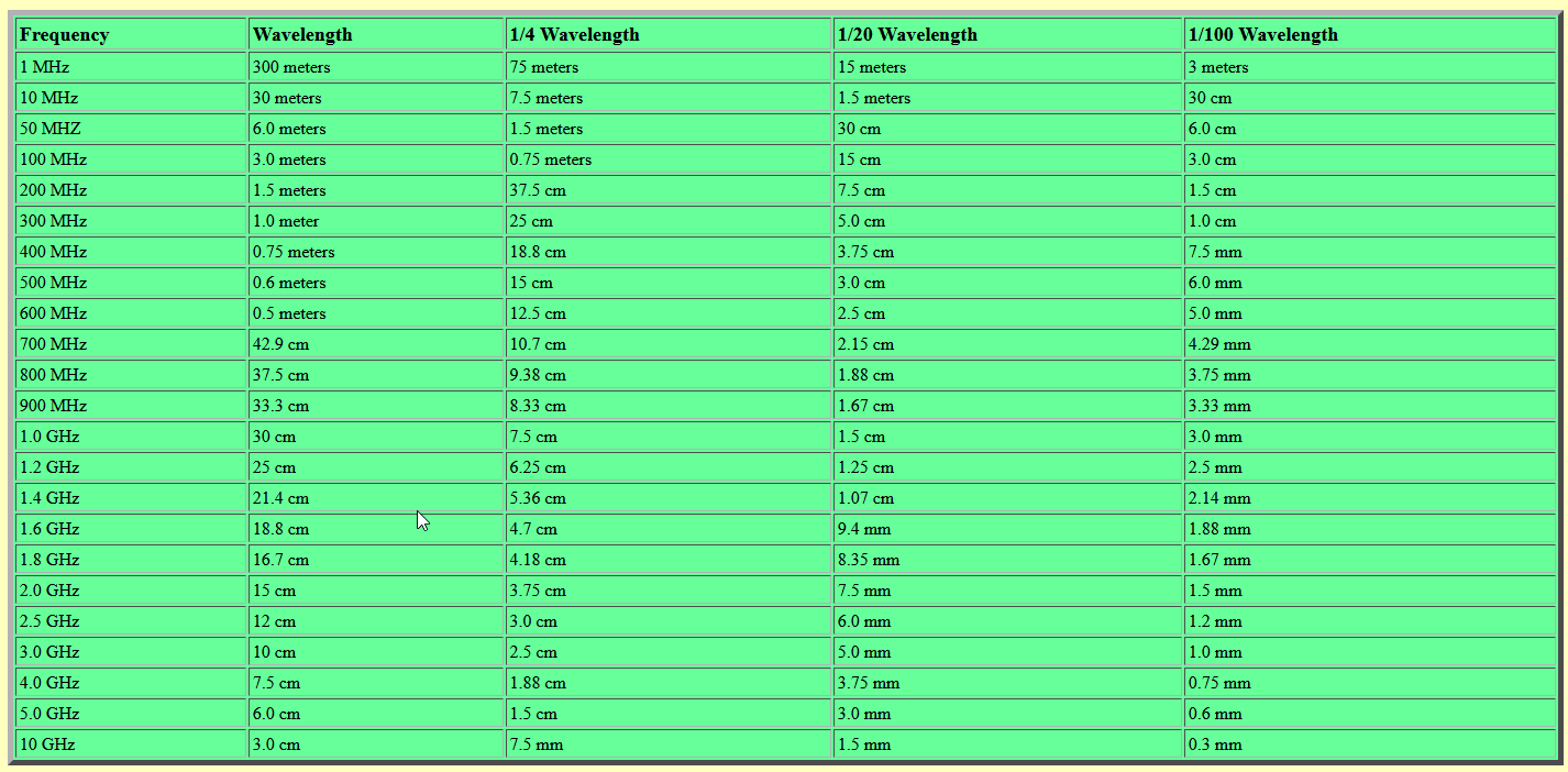
As you can see from the chart above, 2.5ghz has a full wavelength of 12cm, which is about the length that most “rubber ducky” antennas hanging off the backs of wifi routers are… but sometimes you see shorter “stubby” antennas, which are going to be a “harmonic” of the full wavelength… usually 1/2 or 50% wavelength, or 6cm.

Anyway, the point is, EF transmissions are all about electric field potentials. That is not how magnetically coupled devices like passive RFID transponders work at all. In fact, the only reason we use the term “antenna” to describe what are essentially two inductor coils (one used by the reader and one for the transponder) is that they happen to be moving both power and data across a shared magnetic field. Normally when you are placing two inductors near each other in order to move power alone, it’s called a transformer.

To get an inductor “tuned” to a specific frequency, you are basically building a L/C circuit that resonates at your target frequency. In an LC circuit, your inductor (L) has an inductance value which must coordinate with your capacitor ( C ) in order to resonate at a specific frequency. So, you can have basically a nearly infinite number of combinations of L values and C values that all resonate at 125khz. The lower your C value, the higher your L value must be to maintain 125khz tuning. Because it requires two values to match in a specific way, there is absolutely no guarantee that the C value used by the access controller (which dictates exactly what L value the “antenna” must have) will match the C value of your proxmark3… and if your proxmark3 has a different C value, then the L value required to resonate at 125khz will not match the L value of the antenna from the access controller.

Does that make sense?

4 Likes

wow - all makes perfect sense :slight_smile: I will need to read that a few extra times but I think I understand, yeah :slight_smile:

Which means that if a random coil isn’t widely different from the Proxmark’s, you can also tune your LC tank by adding capacitors in series or parallel.

If you can get resonance, then you’ll probably be able to deliver power and get a read. The amount of power, the distance of the read, and the possibility of signal reflections back into the delicate reader circuit are also affected by other factors, though.

If you take a thick gauge coil and a thin gauge coil with the same Inductance, you won’t be able to deliver as much power through the thin one. If you take a flat spiral coil and a solenoid coil with the same Inductance, their field shapes will be different. Also, all capacitors are not created equal. They all have different ESR and some have polarity.

1 Like