Now we’re talkin’. Or maybe a flex PCB tucked inside a real watch strap that has exposed traces that mate with pogo pins inside the watch body.
That’s definitely the plan. We just wanted to do some proof of concept circuits first to see what kind of performance we can expect. I can definitely miniaturize everything on a PCB once we decide if it’s worth it, but I haven’t had the bandwidth to thoroughly test this because of other dev work. Doing it with discrete components makes it easier for anyone to try out, plus it will incidentally leave a DIY/open-source version of the project for others down the line.
This is just for HF, because cheap MCUs often don’t have 32MHz clock speeds. We’re just trying to blast out a signal to light the xLEDs
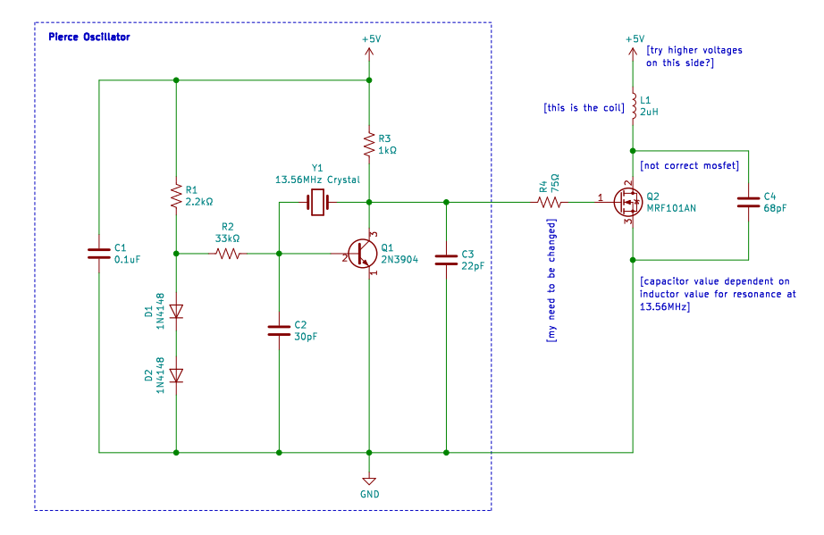
We take a crystal oscillator set up to output a super weak 13.56MHz waveform. We pre-amplify that mV waveform to a few volts using the 2n3904 transistor. Then we take the output from that and put it through a larger amplifier to boost the output even further. It might not work great, but it was an inexpensive solution so I’m willing to try. Our existing plan to source an RF capable mosfet was hitting some snags, so this is an alternative.
Being a practical man, I’ll be repurposing a tabletop reader for my own “bracelet” - which will sit under my arm, to light up my doNExT on the other side. And since it’ll be battery-powered and I plan on making the field remote-controllable, ideally I’ll reuse a BT reader.
Of course, the obvious choice for easily repurposable, easily programmable hardware for my project would be a PM3 + Blueshark module. But… Holy expensive bracelet just to light up 3 LEDs Still, it’s an option, and I might justify the purchase on the grounds that not only will I have a nifty device to turn the doNExT into a morse code display, it’ll double as a handy portable NFC reader I’ll carry on me all the time.
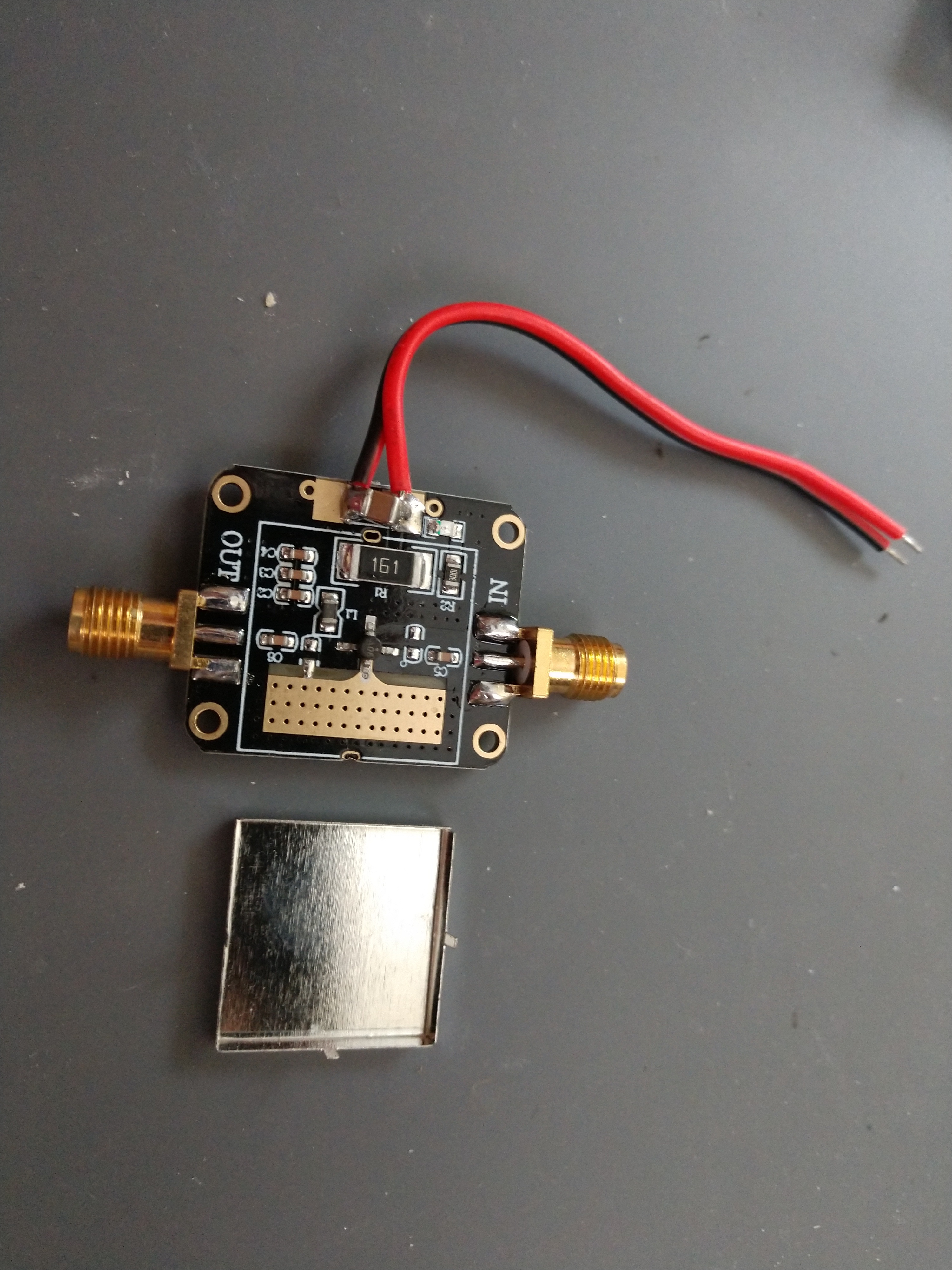
I don’t want to piss on your fire but that device is a MSA0886 MMIC. It’s used mainly as a low level amplifier such as a receiver front-end. Although its Noise Figure isn’t great. If you look at the datasheet its 1dB compression point is about 12dBm, that’s 16 milliwatts! You’ve already got way more than that from a properly designed 2N3904 stage. Also that device is usable up to about 5GHz, you wouldn’t typically use something like that at HF, very good chance of it being unstable.
Yep should be relatively straightforward to do. I guess some might want just the power feature to light LEDs etc rather than a full on reader option. Doing something custom there is a chance of improving on its supply efficiency. I guess the reader designers aren’t that bothered about optimising the supply requirements, as long as it’s reasonable and doesn’t smoke your USB port then that’ll do.
I’m not too sure about that. I mean most of those readers are usually nothing more than a frontend and an enclosure for an integrated NFC chip like the PN533, and those aren’t terribly thirsty for power to begin with, since they may be used in battery-powered devices.
Also, in my case, I’m actually interested in something that can programmatically turn the field on and off. If I were to roll my own, I’d have to add some logic to it anyway to do that. So I might as well go for something that already exists.
Anyhow, for the money and for the lack of headache, I’m happy to charge up a bit more often
Thanks for the heads up. I was concerned that it wouldn’t provide substantive amplification, but it was ~$12 so whatever. I’ll keep it for another project. I don’t have as much experience with far field equipment as I do with near field, if you couldn’t tell
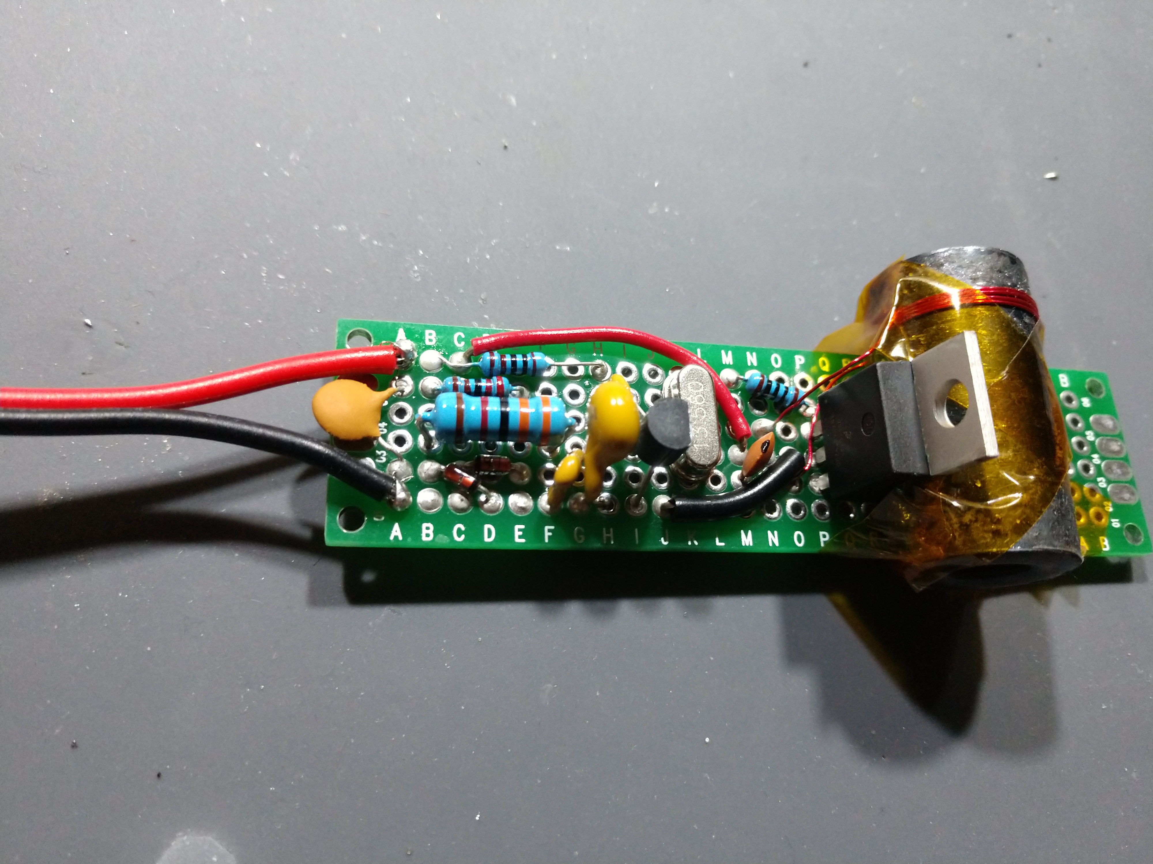
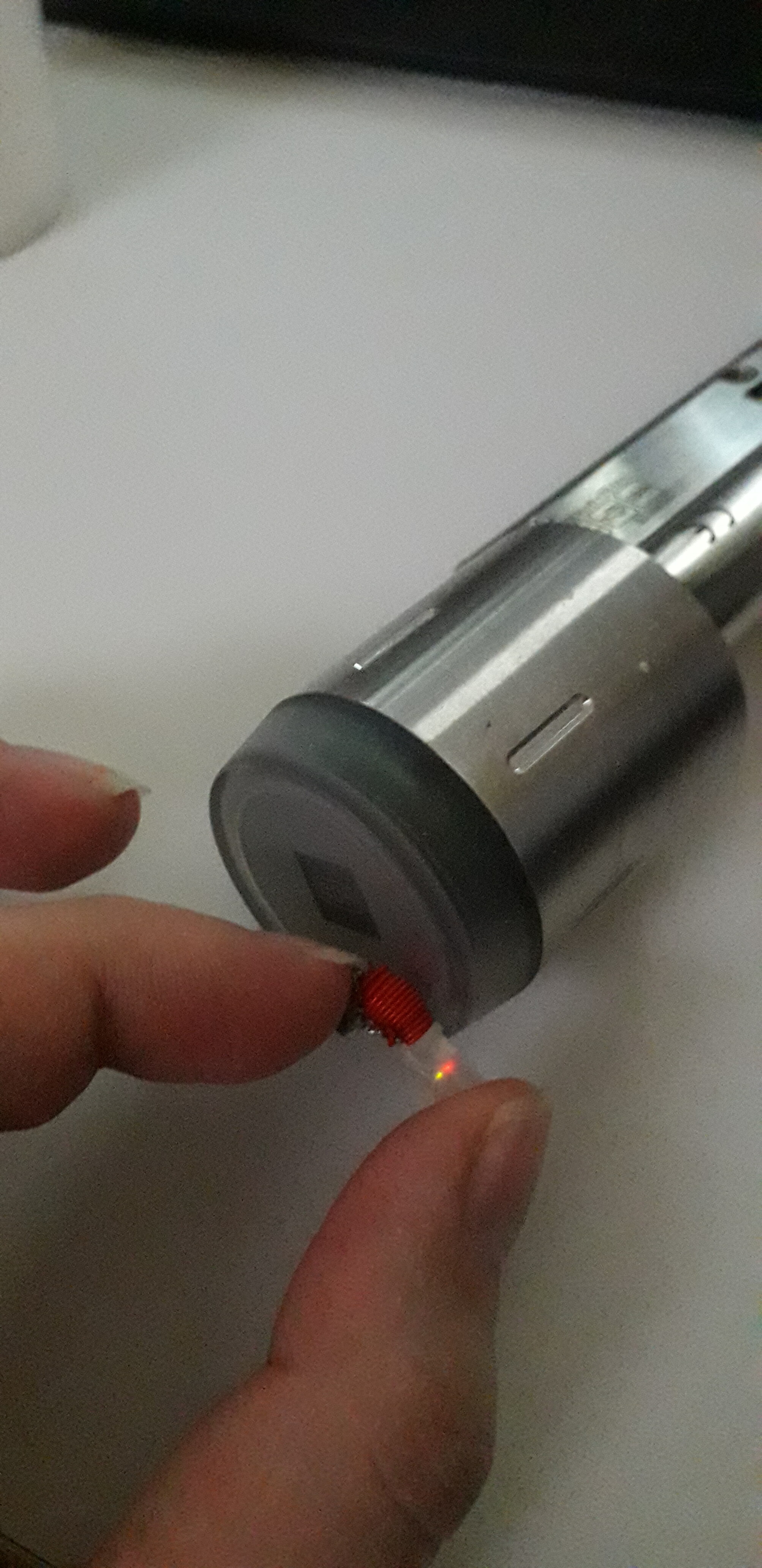
I caved and bought an expensive RF Mosfet in a TO-220 package (I want this first revision to be DIY friendly). The model I bought was the MRF101AN from NXP. I made a nice little protoboard version using the schematic I posted earlier:
I verified that the Pierce Oscillator outputs a 13.56MHz waveform. It has a pk-pk amplitude around 1.3V. That’s not enough, though. The RF mosfet has a minimum Vgs of 1.7V and a nominal Vgs of 2.2V. I stole the Pierce oscillator design because I haven’t biased a BJT in a while, and I certainly never did it with series diodes . If anybody has any insight how I can reconfigure the Pierce Oscillator circuit to allow a greater Vgs across the mosfet, I’m all ears.
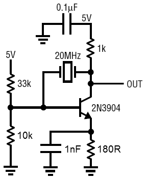
The whole diode thing dosnt sit right with me, personally I would use a colpitts but thats not the point. I think there’s a few issues with the biasing and if im correct the circuit below should fix it and do away with the diodes aswell.
It is very interesting to see what you are all doing here. It my opinion it would be nicer to just keep it simple. I’d aim for a royer oscillator tuned to roughly 13,5MHz. For transistors i’s aim for something like the ss8050 or bc547c because they are really cheap and go far beyond 13MHz. For a very compact version i’d look at KI2302DS. It’s a common smd mosfet thats small and powerfull. I didn’t try it yet but i can try out how high it goes in therms of frequency. When you need power (and i mean lots of power) you can look at the Irf510 mosfets. When you drive it hard enough you can bring it up to 50MHz at 40w per mosfet. I have all the parts here so i could throw some circuits together if you like. I have no xled here to try but i once built a field tester from a bicolour led, some wire and a capacitor.
leumas95 has just started experimenting with the high power prototype I sent him and he was planning to test out the IR510 as a cheaper alternative.
I am working on the light version (on and off). I have everything planned out and parts selected except for the surface mount fets. I’ll look into the ones you suggested.
This is a community effort so if you want to try out a slightly different version yourself that would be most welcome. Having different types will help us settle on the optimal design down the line. Let us know what you figure out or if you want to bounce some ideas around.
The surface mount mosfets can only take about 8v between gate and source so you need to have that in mind while designing the circuit. To the irf510… it’s hard to get the proper one now adays. They are supposed to have a cate capacity between 100-200pF. Alot if the ones i got (from Ebay or Reichelt in Germany) had a gate capacity between 300pF and 2nF. The higher the gate capacity the more power you need to drive the mosfets. Oh and i see i gorgot to mention a bipolar “power” transistor that also easily manages to work above 13MHz. It’s the good old bd139 (npn) and bd140 (pnp) but only the ones from nxp (philips). They have 3w less Ptot thsn the others but are way faster. They are very good for driving the irf510 mosfets in push pull.
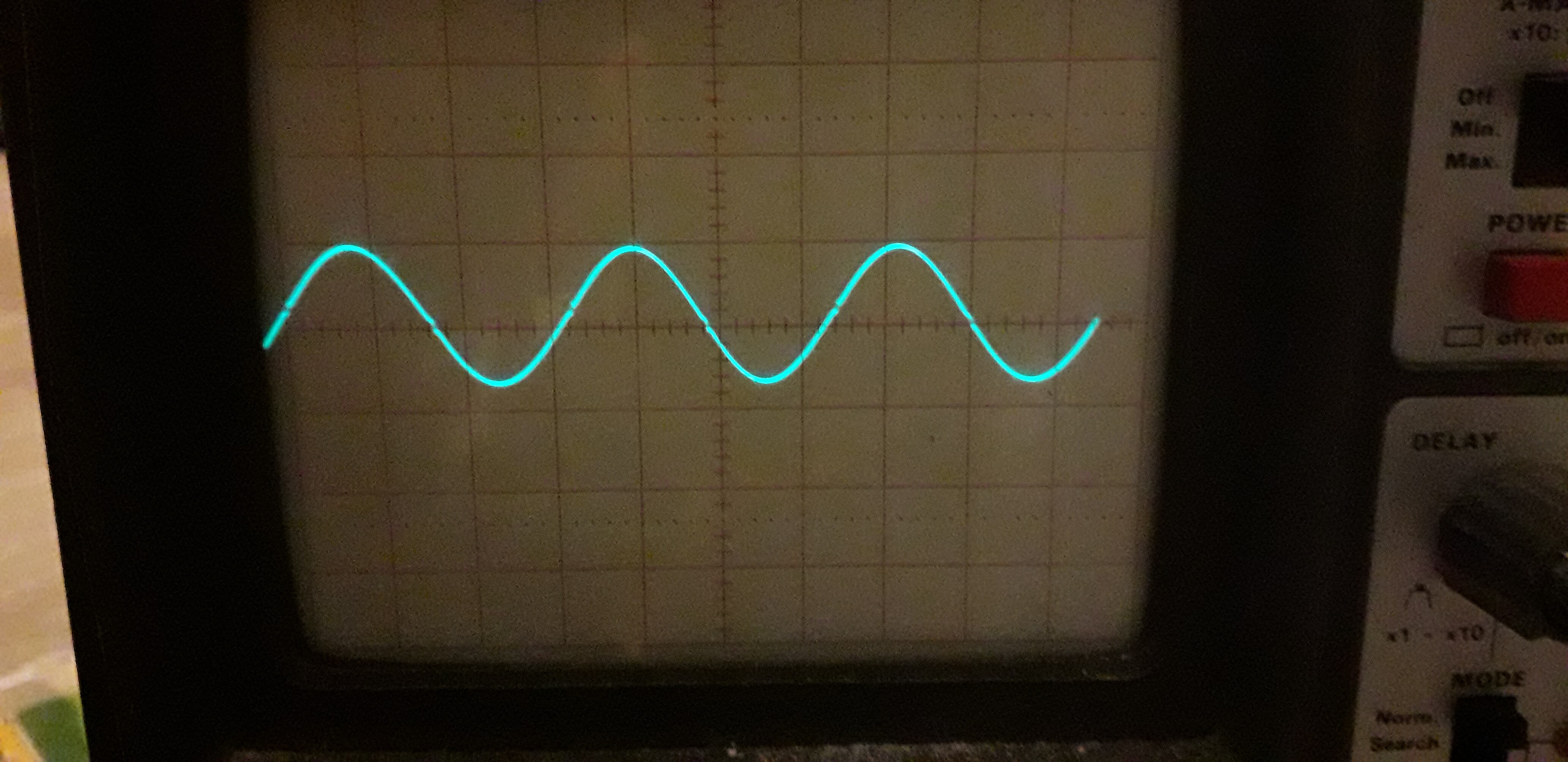
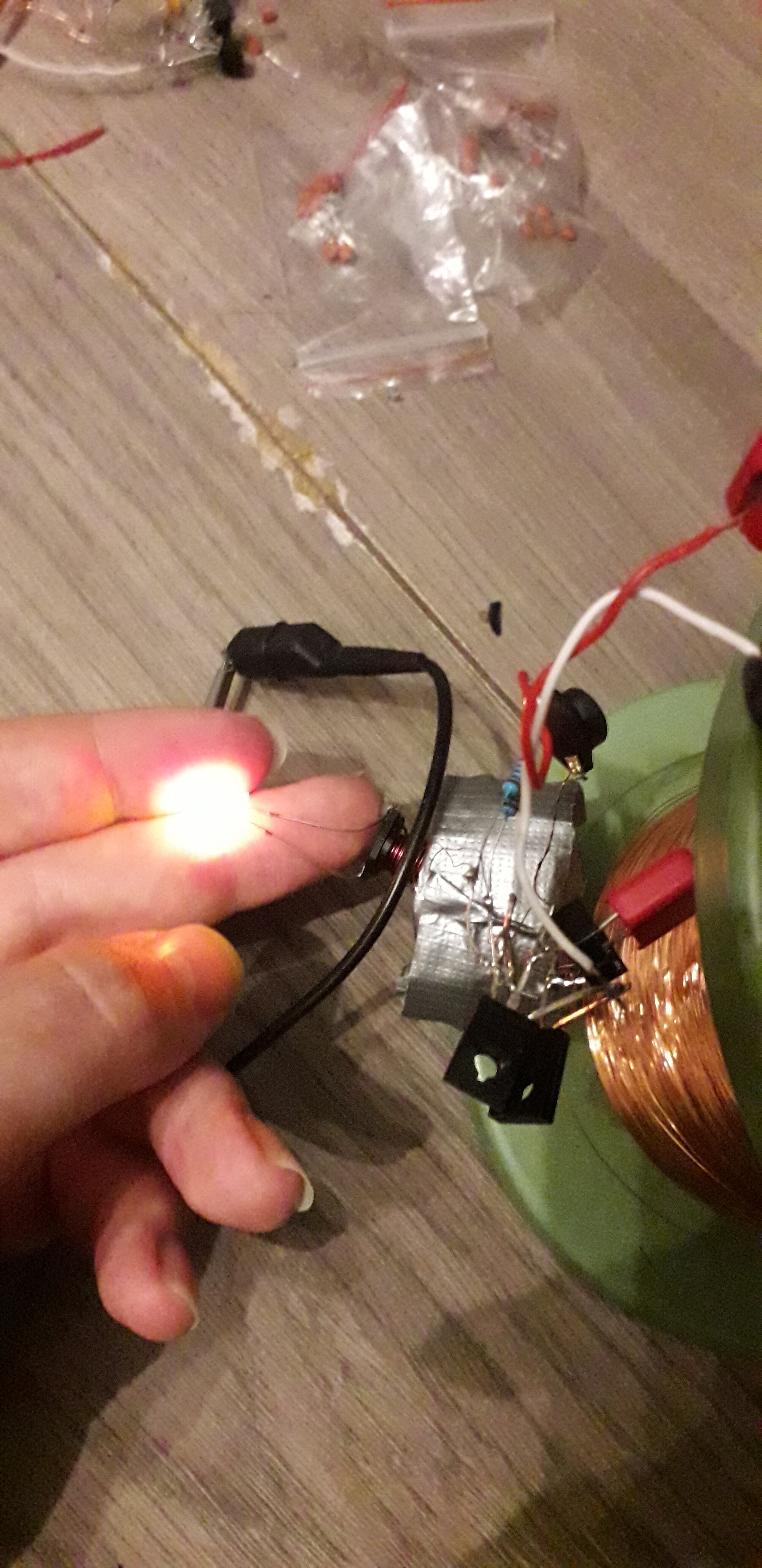
A very quick update: i quickly threw together a few circuits today and i managed to get it to work at 13,4 MHz a d one at 14,3. With a bit of tweaking this will work. The circuit generates a nice sine wave. I still have to order the hf led test kit to try it on that. I have another circuit in mind that i might try tomorrow which is using mosfets. The ones today were with bipolar. I really want to try the smd mosfets though since i want to see how high i can make them go frequency wise.
I’d love to see a schematic if you find the time! I look forward to seeing what you come up with, especially with those SMD mosfets you refer to. Any thoughts on how high voltage your current design / future designs need to be driven with?
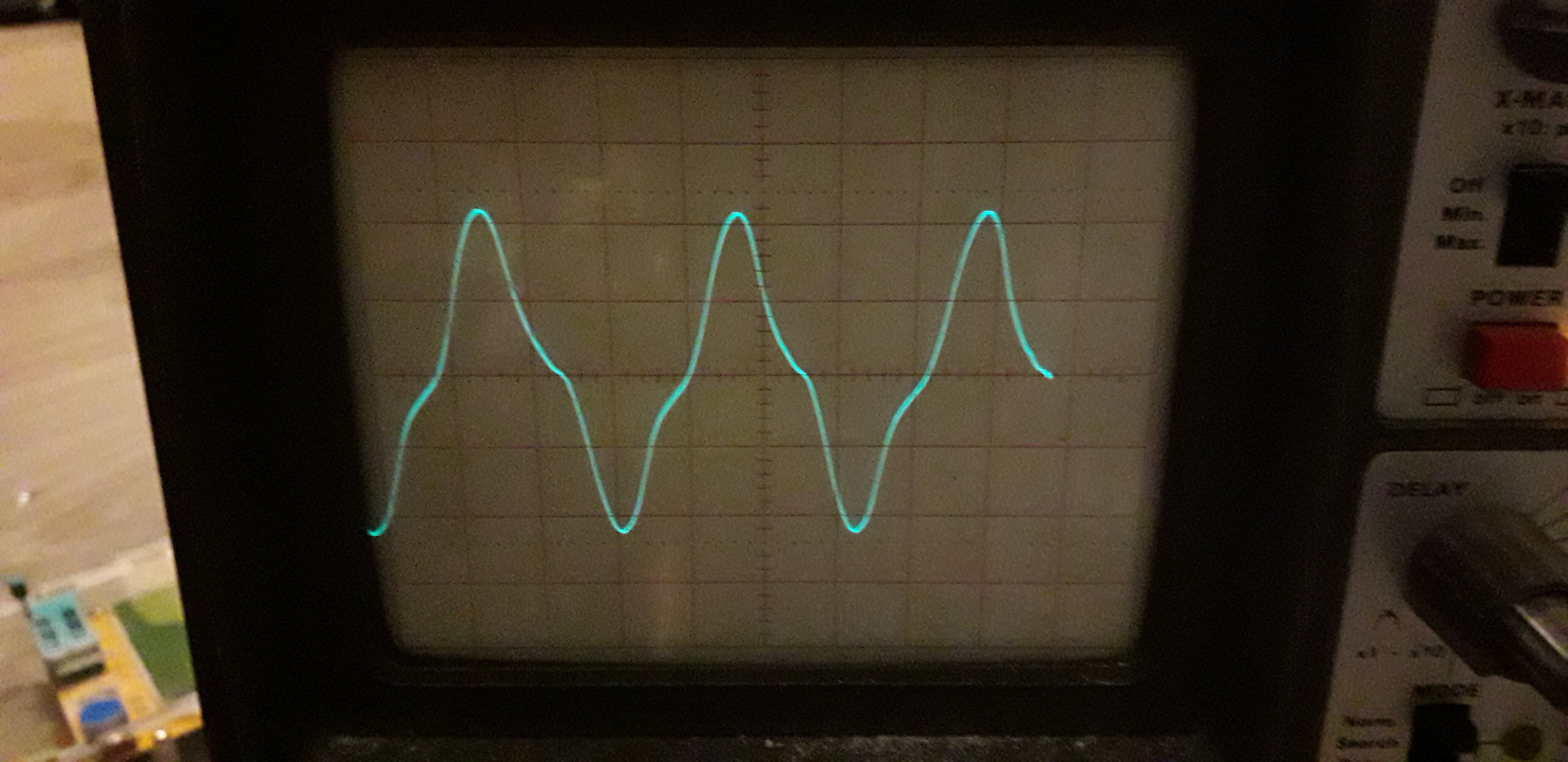
I’ll post circuits when i pinpointed on which cirquit i use. On the one i use right now it works outstanding at lower frequencies but when i go higher the losses skyrocket and tgen drop again. So i might have to try different inductances for the power coil
on 2MHz i get a almost perfect sine wave with good coupling. On a bare bicolour led with only an inductor soldered to it it works quite well at that frequency with high efficiency.
And on 13,6 the transistors get very warm (as i said esrlier probably due to an impedance mismatch between powercoil and resonant capacitor) to the tries with the smd mosfets i didn’t build anything there yet since i forgot how much pain it is to solder smd free wired. I’ll try again today with a different soldering iron and maybe some kapton tape to hold it down
Hey folks, I’ve been following this topic for a few weeks, and I started wondering- does this kind of thing exist in a non-bracelet form? Because like, if I’m just wanting to do something that will make my blinkies light up, I’m willing to just be holding a thing which is the battery + all the other stuff (oscillator, antenna, mosfet (I have no idea what a mosfet is for despite trying to learn about it online and here)) in a single case, which could open up to replace the battery and maybe a switch to turn the 13.56 MHz signal on and off… it wouldn’t even need to be too small or whatever, just fit in my hand, like a pill bottle, or a lighter, or something.
What I’m trying to say here is, if there’s another way to get my blinkies to light up without the use of my cellphone, I’m willing to compromise on the convenience of it in some ways.
Is it technically easy to put something together that just outputs a 13.56 MHz sine wave at a certain power? A lot of this discussion goes above my head in this thread
I can’t help you much with the lower level stuff, but if you’re just wanting to light up your implant in a decently small form factor on the go, something arduino based would be an easy option (and it’s what I use, for showing off my xSIID).
With an Arduino pro-mini and a breakout board (I really like PN532 based boards) + a battery, you could make a decently small solution without having to do much actual work from an engineering POV
Especially if you go for an Arduino board that can do HID emulation stuff, you could always use the same device to act as a wedge reader, password typer, etc. @Vicarious has a great post about the password device he put together in a super nice form factor. That + a small battery and a mode switch (for constant light vs. actual authentication) would make a bad-ass device for showing off blinkies, would have an actual use too if desired, and would cost less than $30.
This is definitely an overkill solution that doesn’t give insane range for lighting up implants (depending on the breakout board, I can usually manage an inch or so with my xSIID), but it’s an easier option, if you aren’t able figure anything else out.
If you do work to build a more low level solution, like those in this post, I’d love to see it though