Yeah, I’m working on a little keychain blaster like you’re describing. We’re calling it the lite version. Leumas95 is still working on the full version. It’s just not high on the priority list right at this moment, but I have most of the BOM worked out. I just need to narrow down my SMT mosfet choices a bit to get the best performance.
2 Likes
@darthdomo, that sounds really cool! I was actually kind of thinking about getting into Arduino recently, they seem like a cool thing to learn and get into for a variety of reasons (like this!). I appreciate the idea and will keep this in mind!
@Pilgrimsmaster , that also looks like a really good solution, basically what I’m looking for, but at $90 that seems a little steep, especially considering I’m mostly wanting it for just the blinkies, not so much the other stuff. Cool find though, and cool website. Thanks for sharing.
@Satur9, very cool! Please keep us updated… if there’s anything I could possibly do to help out with this, I’ll be happy to offer whatever I could do, if anything.
1 Like
oh, and on that note, about what @Eriequiet posted, I’ve got the DT keyboard wedge device sitting on my desk, and I’ve tried holding this in the palm of my hand to see if I can get my xSIID on the other side of my hand to light up, to no avail. I realize that the 13.56 MHz EM waves have very short range, but getting absolutely nothing with even this device is a little disappointing because of how much power is going to be needed to go thru one of these devices just to be able to penetrate my flesh to the other side of my hand.
It’s not really easy to do. It’s still a frequency that can be managed but there are quite a few hurdals. To your question what a Mosfet is: it’s basicly a switch that starts to conduct when you put a voltage on one pin (the gate). The gate is basicly like a capacitor. You charge it to a voltage and it holds that voltage. When the gate has a voltage above 5v it will start to conduct between drain and source. From 5v on to 10v is the region where it conducts more and more the higher the voltage on the gate. Above 10v on the gate it’s fully on. The thing with switching mosfets at high frequencies is charging and discharging that gate 13560000 times per second for nfc. This uses an insane amount of current to do and you are basicly trying to put that current through a wire less than 1mm in diameter. To the range of your reading device: it’s basicly bound to the inverse square law. If you want go double the distance you need 4 times the energy to get the same field strength. What can also influence your range is coil diameter and coil geometry. A flat coil usually doesn’t reach as far as a cylindrical one.
2 Likes
So i had very busy past weeks which crossed my plans to work more on it and try things out. I managed to do a few things though. I tried the second circuit with the smd mosfets and first i couldn’t get it to oscillate and then the tiny smd mosfets died. I also remembered why i don’t like free soldering smd parts. Oh well… yesterday i though why don’t i just order a pcb with it to just put the chips on board and don’t have the pain of free soldering. So i designed a pcb:
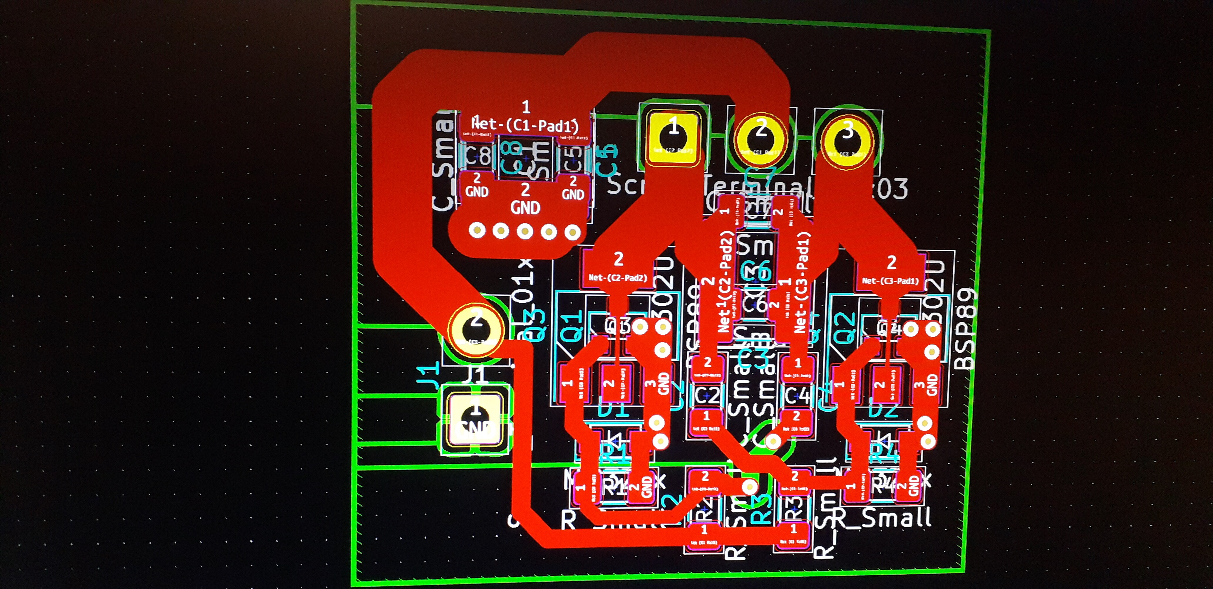
And ordered it on jlcpcb. It has the option of using smd mosfets on two different packages (sot23-3 and sot223) and using either two small caps or one large for the caps that see quite an amount of ripple. One thing that worries me though that it might not reach 14MHz is that it probably has quite a bit of capacity from the tracks alone. I’ll update you on that when the circuitboards arrived in about 2 weeks and i got around to populate one or two. Also i got the xled field tester keychains now so i could try the nfc one on the other circuit i was working on
So much to updates right now.
5 Likes
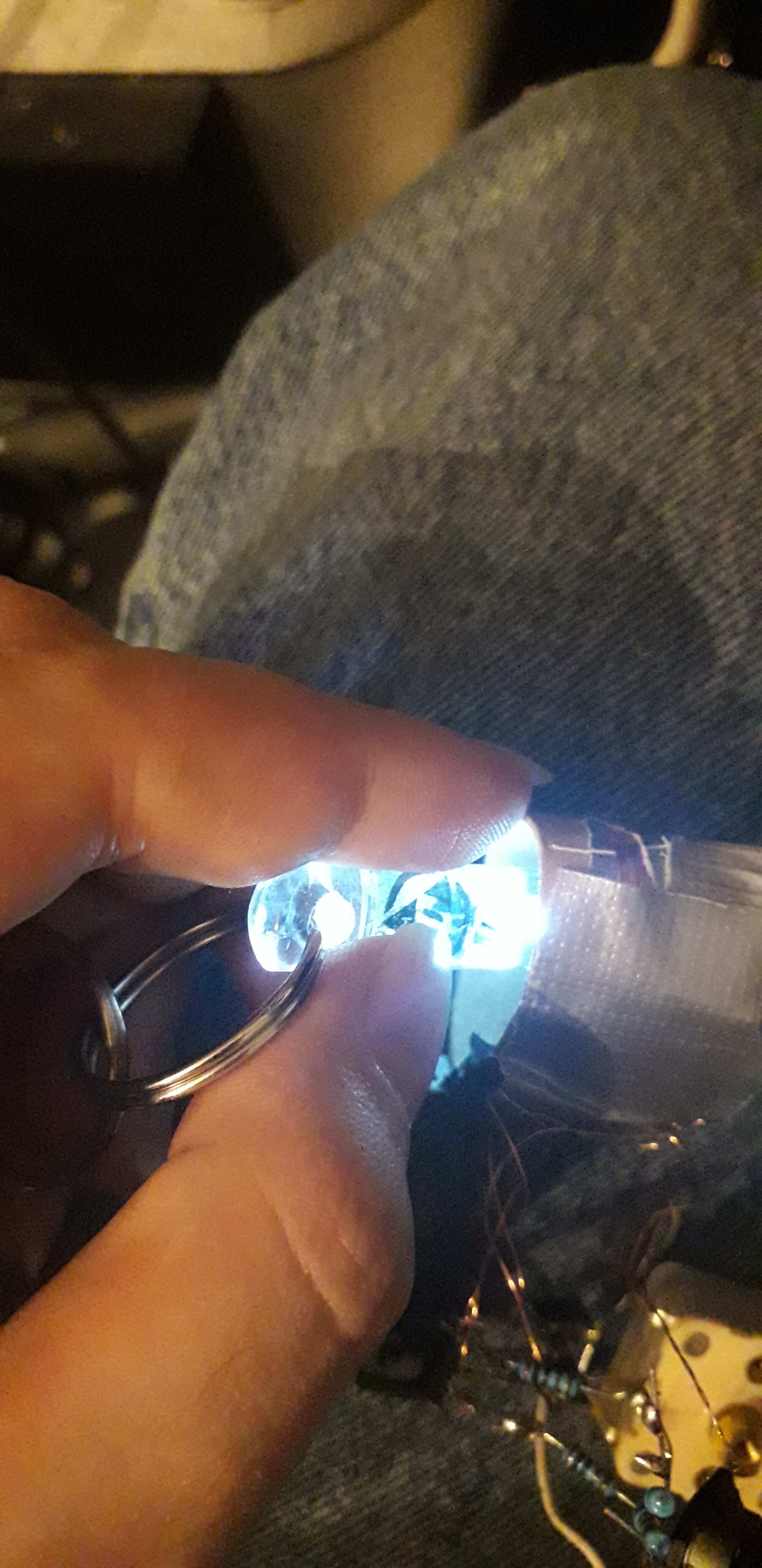
Very nice, not sure if I’ve ever seen an xFD glow that bright.

Lemme d-rail 4 a sec.
so there is nothing to limit the current on a xled?
That means they re easy to blow out? (as if there qould be some regulation)
so you must trust the reader to not kill it?

Yep pretty much. That’s why the xsiid is a good option.
1 Like
For the LF xLED there’s basically no protection, but for the HF xLED the impedance (frequency dependant resistance) of the coil is very high. I doubt you could burn one of those out even intentionally.
2 Likes

Please do try. If you have a function generator that can accommodate 13.56MHz I’d be interested to see your results. You might also want a VNA to find the actual resonant peak to deliver max power. It’s a bit off from 13.56, IIRC. I posted a video that explain how to set a cheapy one up for that kind of testing here
EDIT:
I calculated out that the impedance of the HF xLED coil should be more than 240Ω at 13.56MHz. The LED in the xLED is white so it’s probably something like 3.2V forward voltage and 40mA forward current. Since the negative portion of the AC waveform induced by a reader is cut off by the diode, that means the Pk-Pk voltage that would need to be induced into the xLED by an external device would need to be 20VAC to even meet the rated values, nevermind exceed them. I’ve only been able to induce 6VAC Pk-Pk in an LC tank circuit under ideal conditions, and the fact that it’s a periodic waveform means there’s time in between the pulses for the junction to cool. You might be able to burn it out, but I really don’t see how.
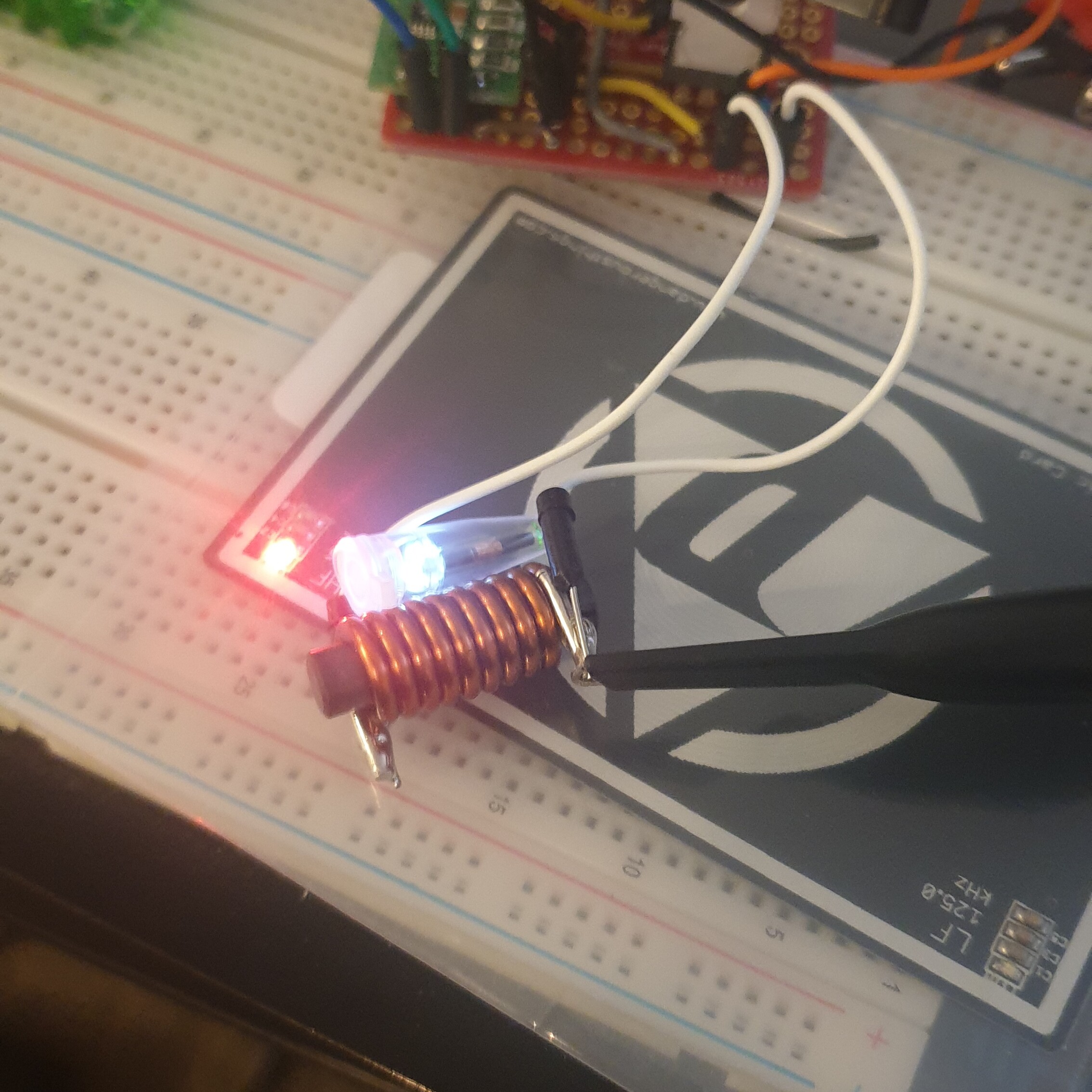
The reason why i bought the keychain is that i’m also worried to blow it. And i’m pretty sure i could do that. By the way… a friend of mine has a frequency generator that can output 500w of rf power at 13.56MHz without breaking a sweat. Anyways it’s not as bad to break the keychain than it is to break an implant so i went with the key chain. The xLed in my test got really quite bright at the sweet spot at the coil despite it was not being driven the right frequency and i only input like 3W of power into the circuit.
Feel free to give it a shot. If you can fry a field detector keychain and tell us how you did it then I’ll make sure Michelle sends you a replacement or two.
Hi there!
I have been a bit dormant on the forum and only got back to this project recently…
I recently ordered some PCBs myself, the design works but I am not hitting the gate-source threshold voltage of the MOSFET/s I am using.
The circuit works it just seems to not open the gate fully so gets hot prematurely and limits the power.
The voltage coming out of the oscillator is only going up to +480mV, the MOSFETs I have been using all need 1.7v or 2v (Tring a few) at the bare minimum.
So I decided to grab some BD139 and BD140 and use them to try and get the voltage up before going into the MOSFET/s after seeing your post, I however missed this:
I also can not find them available anywhere or anything that would work as a decent replacement.
I need to boost that 500mv to at least 2v, so any advice is welcome!
3 Likes
Just made new prototype on a protoboard using an programable clock. The signal is not a nice smooth waveform but it still gives me a 13.5MHZ clock. Using this I did get the MOSFET to operate correctly but since I am only hitting +2.5v it’s not letting much current through which is limiting the current significantly, but I can now run it off 5-30V for extended periods but only with 60ma draw.
5 Likes
Further updates, I can now dump ~5A through my circuit, my scope is reading 13.6MHz off the connection to the coil but no LEDs seem to light up which seems very strange…
Edit cause can’t post another reply:
Well I fixed it…
With some tweaking I got it to light stuff up and not draw the full 5A my power supply can deliver lol.
The MOSFET gets very hot infact I think I blew it… But also I was pushing it fairly hard with a fairly small heatsink…
4 Likes
Reply bump
2 Likes
I get my nxp bd139 and bd140 from ebay. I just a new pack yesterday. I might work on the circuits again today (but i think i forgot the field testers at work) so i’ll have to see.
The first pcb’s for tests are ordered. I’m currently waiting for their arrival. I also bought new field testers since mine didn’t appear again (must’ve lost them somewhere ![]() ). Tomorrow a friend comes over and brings some power rf stuff with him to try and fry the nfc field tester. We will use a matching circuit that will be able to dial onto resonance to get the absolute maximum coupling. I’ll not get my hands near that coil since i fear of damaging the nfc implants i got. Also i found some more mosfets that should be able to handle the frequency easily for the bracelet version. One of the mosfets comes in a sot223 housing but can handle 6w of heat dissipation with only slightly higher gste capacity than the irf510. It would also be able to run from 5v with it. Anyways… that much to the update so far
). Tomorrow a friend comes over and brings some power rf stuff with him to try and fry the nfc field tester. We will use a matching circuit that will be able to dial onto resonance to get the absolute maximum coupling. I’ll not get my hands near that coil since i fear of damaging the nfc implants i got. Also i found some more mosfets that should be able to handle the frequency easily for the bracelet version. One of the mosfets comes in a sot223 housing but can handle 6w of heat dissipation with only slightly higher gste capacity than the irf510. It would also be able to run from 5v with it. Anyways… that much to the update so far
2 Likes