Homemade Spark 2 xAC

First, I would like to say thank you to Vivokey because this has been an intense but wonderful learning experience. I would also like to say thanks to Vivokey for maintaining the api2 endpoints absolutely free of charge.

Recently I have noticed an influx of users asking what they can do with their Spark 2, well this project can now be added to the list of answers! Provided you can solder a few components together and upload a sketch to an Arduino, this project will provide you with the ability to use Vivokey’s api2 server to access the cryptographic functions of your Spark 2.

A successful run through of the sketch(successful mutual verification of the Spark 2) is shown by pin22 of the ESP32 turning on for 1 second. If you would prefer something else to happen, those lines of code can be changed to just about anything. For now, pin22 can be attached to a relay which should mimic the good ol’fashioned xAC.

Sequence of events(to temper everyone’s excitement):
1.User touches capacitive wake-up pin4. (onboard LED turns on)
2.Approx. 3 seconds for WIFI connection.
3.Get-challenge received. (onboard LED turns off)
4.Starts 10s timeout scan. (Scan your Spark 2)
5a.If successful, pin 22 turns on for 1 second
5b.If failed, “Fail!” is printed to console.
6.ESP32 goes to sleep. (rinse and repeat)

Since this project was designed to be battery friendly the ESP32 will sleep between each scan. Every time the ESP32 wakes up, it will need to reconnect to the WIFI which takes most of the programs “awake” time. If you would like a faster process time, the WIFI connection would need to be sustained therefor increasing the power draw significantly.

Required components:

ESP32 DEV-KIT V1 (30pins):

PN532:
https://www.elechouse.com/elechouse/index.php?main_page=product_info&cPath=90_93&products_id=2276

GitHub Repository:
https://github.com/AbbottDSmith/ArduinoVivokey
GitHub - AbbottDSmith/ESP32VivokeyLibrary

Inside the Github repository is an Arduino sketch(.ino), an arduino_sercets file(.h), and a PCB Gerber(.zip) The PCB Gerber is only used to eliminate wires, it is not required.

SET-UP:
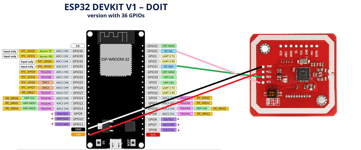
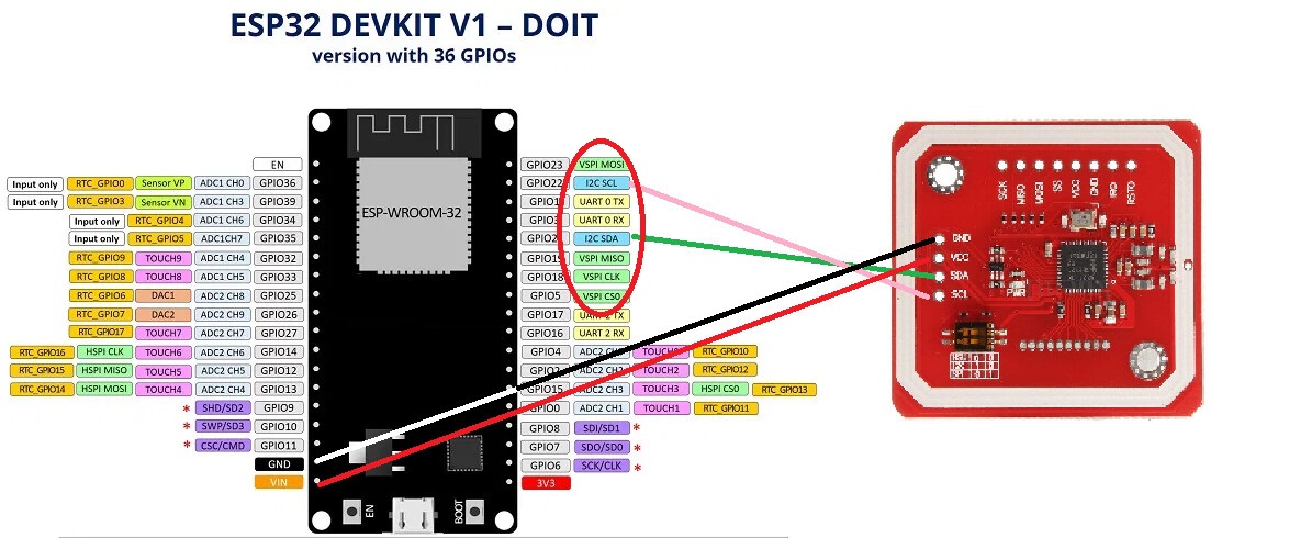
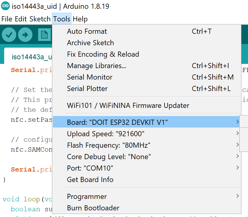
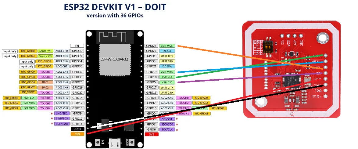
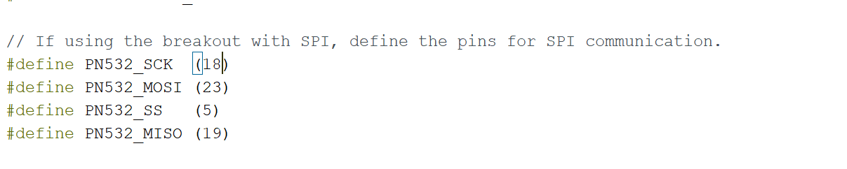
1.After wiring the PN532 to the ESP32 by route of the VSPI pins (SS pin = pin5). Download and install each dependency into the Arduino IDE. (ArduinoJson and PN532 Libraries)

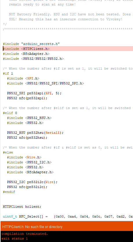
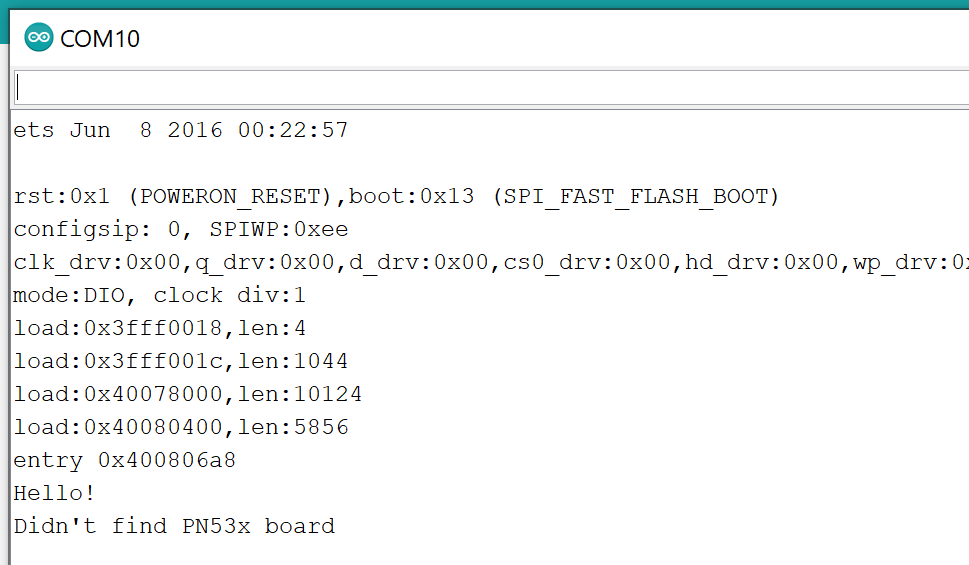
2.By default the ESP32’s SPI clock speed will be 30MHz. The PN532’s maximum SPI clock speed is 5MHz. To fix this problem, we can either slow the ESP32’s CPU by using the Arduino IDE, or we can edit the PN532 Library to set a larger clock divider. Since lowering the ESP32’s CPU speed to a suitable speed will disable WIFI/BLE communication, a larger clock divider is the only option. To do this, a change must be made to the PN532 Library. Open PN532_SPI.cpp and change:

_spi->setClockDivider(SPI_CLOCK_DIV8);

To:

_spi->setClockDivider(SPI_CLOCK_DIV64);

Now when the ESP32’s CPU clock speed is 240MHz, the SPI clock speed will be 1/64th = 3.75MHz. Perfect for a PN532.

3.The arduino_secrets file must be edited to add your SSID, PASS, APIKEY, and ROOTCACERT. Only after the initial boot can “VERIFYID”(member-id) be added. The VERIFYID string will be obtained from the initial console’s output. In other words, do not worry about leaving VERIFYID blank for the initial boot up.

4.After running the program once and successfully obtaining VERIFYID, fill in the missing variable in arduino_secrets. It is then recommended, not required, that the user ERASE the lines of code that print VERIFYID to console. These lines will be marked inside the .ino to make them less difficult to find. Finally, reupload the finished files to the ESP32.

Set up is slightly complicated admittedly. If anyone can make sense of what I have written, and then create a tutorial, that would be super appreciated. To say “I have faith in this community” would be an understatement.

Side note:
A reminder to anyone who needs it; check your byte order! This project would have been out a month ago if I knew that my UID needed to have it’s endianness changed. I am sorry to all the lovely patrons of this forum that I bothered for help. I obfuscated my UID in all of my posts that asked for help, which made it impossible for anyone to actually solve my problem, my bad… I am including this line of code because it has had a major impact on me.

uint8_t bigEndianUID[] = {uid[6], uid[5], uid[4], uid[3], uid[2], uid[1], uid[0]};
9 Likes

Update: I’ve added FastScan.ino which maintains a wifi connection and gets a fresh challenge every 25 seconds to be ready to scan at any time.

FastScan.ino, unlike the battery friendly version, does not require the use of a ROOTCACERT because it skips the SSL verification all together for extra speed.

I was also able to remove the ArduinoJson Library dependency, so the only remaining dependency is the Seeed-Studio PN532 Library.

FastScan.ino only requires a SSID and PASS to connect to your WiFi, as well as an APIKEY to connect to Vivokey.

FastScan.ino would be my recommended example sketch.

2 Likes

wonderful work!

It’s not work when you love what you do! Thanks for the appreciation!

A little peek at where this project is going now.

I have ordered this different ESP32 chip and now have to wait for it to arrive so I can start testing. Once my code is airtight, I plan on designing one last pcb that will have the ESP32-S2 pick and placed by jlcpcb.

Similar to the pin programming of the xac, a dip switch will be placed to toggle between “upload sketch mode” and “in use” mode. Making it so the only soldering required would be to attach the PN532 SPI pins.

It would be nice if I could avoid all soldering by including the PN532 on the same board, but I do not believe I am able to redesign a PN532 with a new pcb coil antenna.

2 Likes

I know the feeling… I would love to combine parts from a trinket m0 (samd21), a 2 port USB hub, and a PN532 onto a single PCB, preferably leaving several I/O ports free for additional uses.

There is no way that I am capable of that at the moment though.

The idea of a one board microcontroller/NFC reader with the ability to program it for whatever uses you have (and I think the USB hub makes burying it in a keyboard much more viable if you want) would be a great enabler for many of these software projects.

Of course the esp route gives you wireless instead of USB, perhaps two boards are needed… :slight_smile:

I can offer you a hand with that as soon as I have more time available.

1 Like

Would you be able to elaborate how you have the pn532 hooked up to the esp32 please? I don’t know which pins are the VSPI pins. Ground is fairly obvious to me but I don’t know where to connect the other 3 wires without risking releasing magic smoke.

my current configuration

Thanks :slight_smile:

There will be a total of 6 wires coming from the PN532 to the ESP32.

PN532 SCK = VSPI CLK
PN532 MSO = VSPI MISO
PN532 MOSI = VSPI MOSI
PN532 SS = VSPI CSO
PN532 VCC = VIN
PN532 GND = GND

I put a red circle around the VSPI Pins.

I used a 30pin ESP32 for my project but it should work with a 36pin too.

Friendly reminder: Make sure the physical dip switches on the PN532 are flipped to SPI mode. Also make sure to edit the PN532 Library to adjust the ESP32’s SPI clock frequency to 5MHz or below.

1 Like

The diagram shown has the connections for I2C marked. The SPI connection uses the other row of holes at the top of the board as shown. (As opposed to the higher density connector at the bottom of the image).

2 Likes

like this?

Looks good to me!

1 Like

i am stuck again :frowning:

The steps I’ve done so far:

-wire everything up like my previous post

-open the fastscan example sketch

-click sketch>include library>manage libraries and added “adafruit pn532 by Adafruit” and “ArduinoJson by benoit blanchon”

-navigate to documents>Arduino>libraries>pn532_spi and edited the file there named “pn532_spi.cpp” to change this line as directed

image

i am so lost :laughing:

The first step with any Arduino board is to install the board from Board Manager, I believe that is why you are missing HTTPClient.h

You should not need to download ArduinoJson anymore, it is no longer a dependency.

I also don’t think you downloaded the right PN532 Library. I used SEEED Studio’s PN532 library but if the only error you get is “HTTPClient.h is missing”, ignore this last statement.

1 Like

What should I search for in board manager? I tried esp32 but nothing is showing up

Here is an awesome tutorial.

2 Likes

So I’ve managed to install the esp32 board into the ide as seen below:

And I have my pn532 wired as shown here:

Where I am currently stuck at is when I try compiling the example sketch iso1443a_uid, it compiles unsuccessfully, when I try and upload to the board I get this…

:frowning:

1 Like

Looks like the compiler doesn’t know which variable called “nfc” to use. Just comment out the line below: // Use this line for a breakout with SPI connection so that the “nfc” variable is only defined once.

You will also need to adjust the PN532_SS variable to match the pin that it’s wired too. (5)

1 Like

Thank you for your help! That line was actually already commented out and I thought i needed to uncomment it based on the text above it. I am definitely out of my element here, but trying lol


does this look right?, nevermind, clearly its not right because in the serial monitor I am getting “Didn’t find pn53x board”

1 Like

Have you made sure the physical switches on the PN532 are flipped to SPI mode?

1 Like