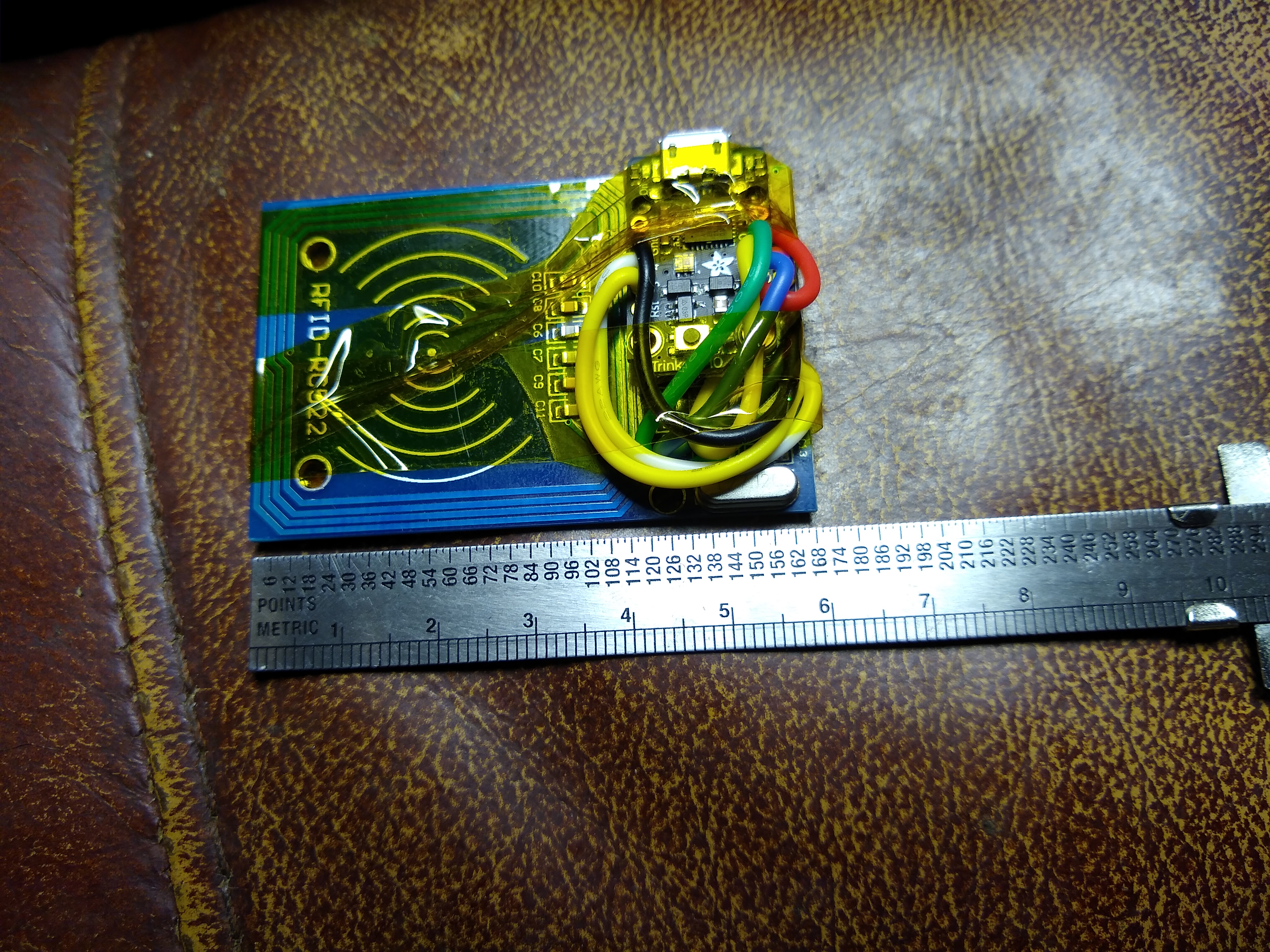
The rc522 is a high frequency reader. I need to improve the NTAG detection as the standard library decides that they are MiFare Ultralight or Ultralight C.
The Trinket M0 is an interesting little chip.
The rc522 is a high frequency reader. I need to improve the NTAG detection as the standard library decides that they are MiFare Ultralight or Ultralight C.
The Trinket M0 is an interesting little chip.
r.1 of the case:
As small and compact as possible, it needs to fit in my PM3 case for carry on (it fit right into the “duvet/step” of the PM3 easy)
A few minor tweek and I’ll release r.2 into the wild.
It looks good.
How is the read range?
thanks, Ill measure it with a card (Don’t have an implant yet … soon™ … but not soon™ enought)
Also, seam like the newest version of the code print the password and UID at the same time.
When there is a password store on the chip, the read print the password then the UID on the following line , was this intentional?
No, I’d better fix that. It is obviously not returning the right value from the password search.
Thanks for the heads up.
its returning the password, but its also returning the UID
Try the latest version.
It looks like it is working now… I’ve also added some extra files that are irrelevant (the unlicense, a contributing file and some templates for bug reports and feature requests)
I have the same behavior …
Ill post caption when i get time to put it together.
I have increased the antenna gain and shifted the delay. I am sometimes getting the wrong answer (about 1 in 20 times) and I think it is because of poor coupling.
See if that works for you.
Ok, made a third card to test all 3 possibilities (all MF Classic 1K):
I love the color change when reading.
Edit: I consistently get 1" range with a full size card (from the top or bottom).
Well, I just got a second set of hardware so I will build that and try and replicate exactly what you are seeing. I am using keyfobs for testing, but I definitely wasn’t getting those results.
I will try and replicate your layout to see if it seems to be interference between the two boards.
Yes, the colour changing light is very handy for testing.
I will try creating some cards as well.
I can also test some ntag stickers and buttons.
If I can’t replicate it, I will create a branch with the third mode disabled and we can see if that fixes the password mode for you. If it does then I will see what else I can try to fix it.
I’m surprised this is happening now, but better now than six months down the line.
I went back with the older codes and the first 2 versions works.
Do you have a way to identify the rev?
Major edit:
Edit #2:
I played with adding a delay between the check, and it helps a lot (up to 50/50)
i removed the UID type and it works when it read, i think it has issue going through the card (it seam like its not reading anything, the card has to be presented several times before a read happen)
went back to the last rev with the added delay, and when leave the card in from of the reader, i glow red, enter teh UID, then switch to green and enter teh password.
I really think its a read speed issue. Could we have the read of the card happen 2 or 3 times before “giving up” and writing the UID (im not sure how to test it myself)?
I want one of them devices when you’re done - if it ever goes for sale.
I can have that piece of code loop a few times.
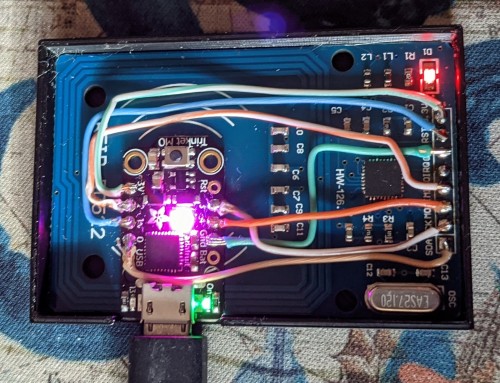
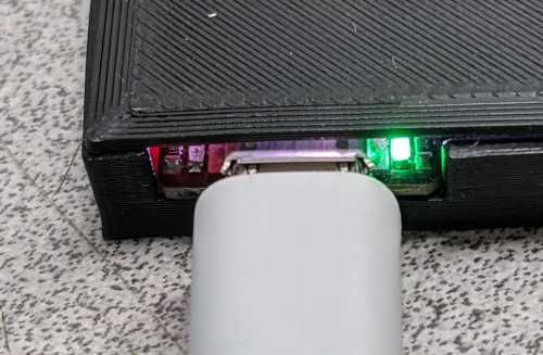
Edited to add: Added a triple loop within that check, set the antenna gain back and checked with two different layouts to see if I could replicate (I can) and reduce (I can) the read errors. See the next image for the layout I ended up with. This keeps the footprint within the size of the RC522 board. (109 x 168 point, or 9½ x 14 pica, or 4 x 6 cm or 1½ x 2⅜ inches)
Having played with layout on my build I suspect the reading problem is the layout. I think a better layout is to clear the antenna and move the Trinket to the top of the RC522 board. I put Kapton tape on the back of the Trinket and then used some more to tape them together.
I still get the occasional misread (less than 1 in 10) when I put the token badly in place.
Here is a picture of my layout.
You are absolutely right!
I moved my m0 to the same location and I get well over 9 out of 10 good read. I’ll re-download your latest version to the trinquet tonight (I added some delay in the hope of getting better reads, but it didn’t work until I moved the board location).

I’ll adjust the case and should have something usable in the next couple of weeks …
Edit:
Reloaded the GitHub file and so far it’s been doing great ![]() , not a single bad read for about 50 present (~30 with password on chip and ~10 of UID and ~ 10 with password on reader)
, not a single bad read for about 50 present (~30 with password on chip and ~10 of UID and ~ 10 with password on reader)
I’ll finalize the box for this layout.
At the risk of seeming silly, is it possible to make the box only cover the top part of the RC522? So have the antenna sticking out? That would allow for better access to the antenna, and save on print medium. The other option would be to have a full size lower tray as shown in your picture and an upper cover that only covers the trinket and top of the RC522, again leaving the top side of the antenna bare.
I have never designed a 3d printed case but I feel this would protect what we want protected but leave the antenna more exposed.
If the person printing has a dialed in enough printer,
It’s possible to make that portion only 1 layer (.2 print units)
Will need a good print surface and first layer control
Not silly at all, i have 3 designs in mind, and one of them has the top of the antenna exposed for this exact purpose.
The third one (may or may not happen) would be snap together instead of glued, but a bit bigger …
I print with the first layer under 0.005" that’s way to thin to hold on its own. Under 3 layers there is no integrity (first layer is supper thin for bed adhesion then one layer in each direction do it doesn’t fall apart)
So I print the top and bottom at 3 layers, which comes out to 30 thou; the LED still shine through the black plastic …
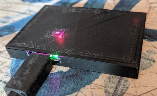
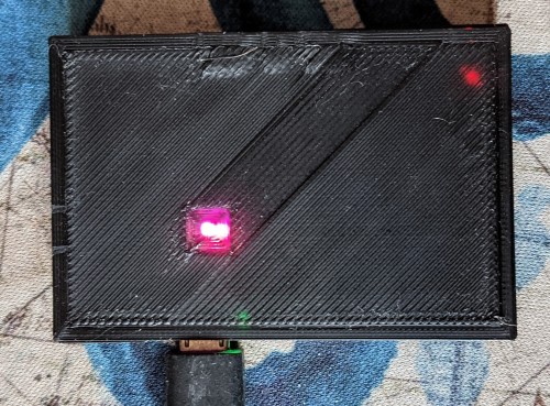
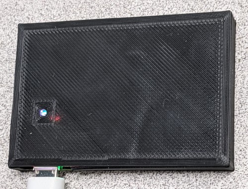
Case update:
First run at the full case … Misaligned the led hole …
Once I confirm this is good, the half enclosure should be soon™ behind …
Also, haven’t had any issue with the new layout ![]()