KBR1 Laptop mod

Here I go again…

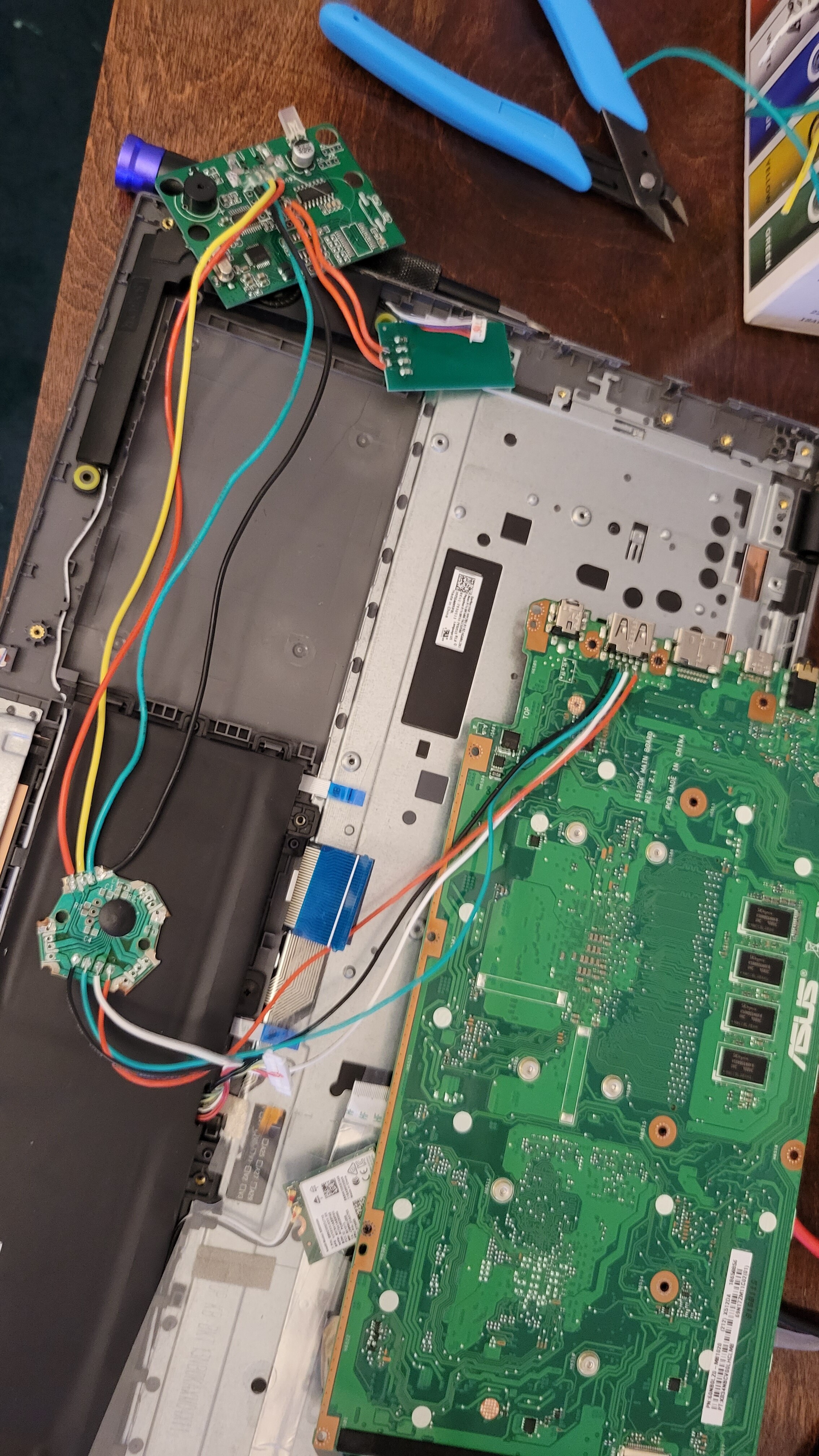
I’m at a holding point for the car key mod, so I’m going to start another project. Turns out I again hit my normal snags so hopefully I can reach out to y’all and get an answer.

Here are some photos of what I’m doing.

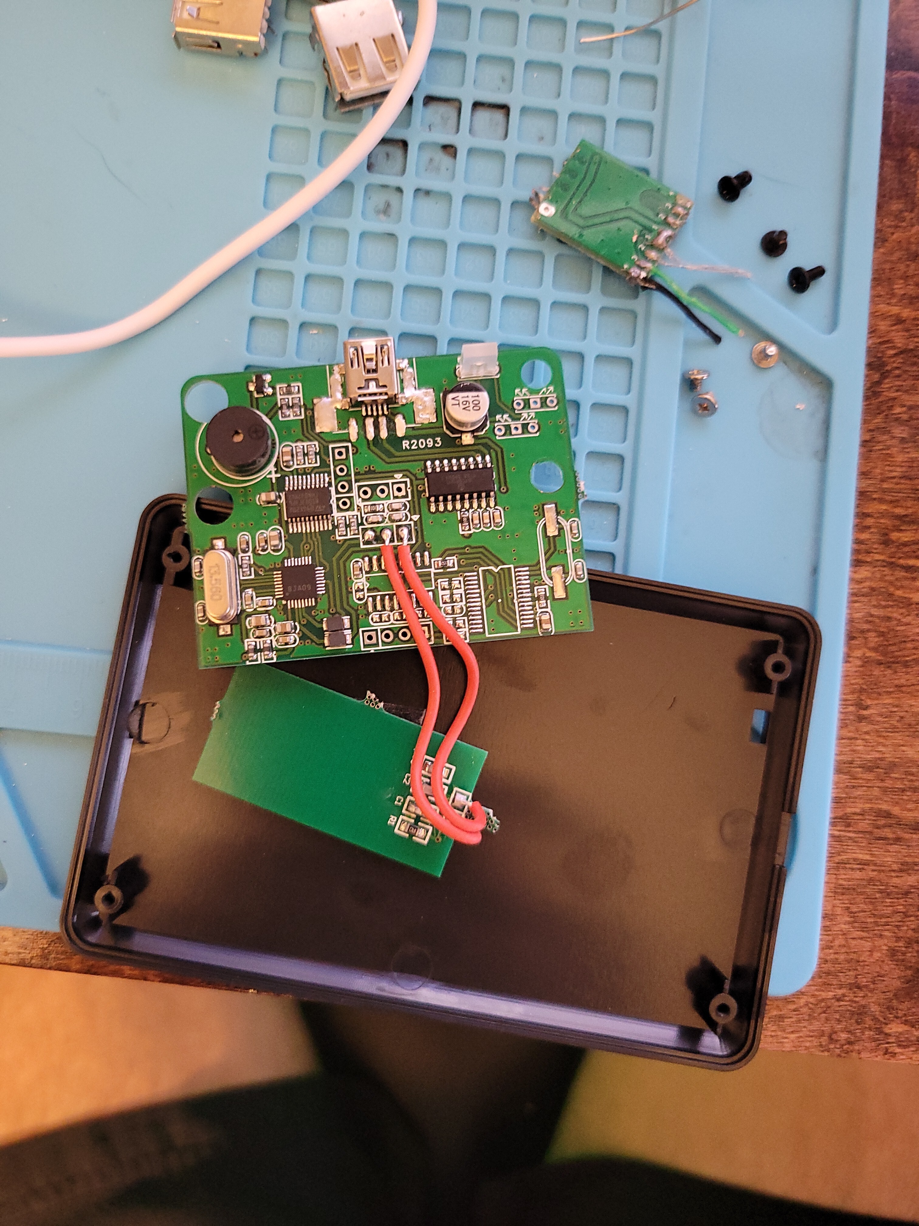
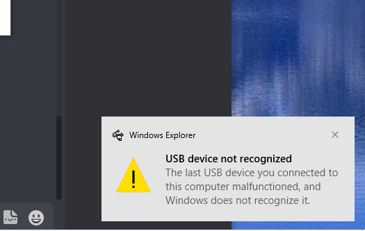
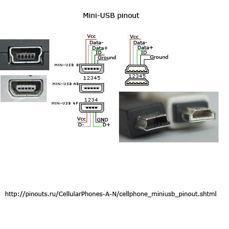
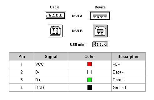
So now on to the question. I thought that soldering wires to the 4 pads behind the USB port would work great, but it apparently does not. basically, the windows machine says " Device Descriptor Request Failed"

Am I missing something simple?? do I need to bridge something?

1 Like

What’s the board with the bonded die on it that is in between the KBR1 and the USB port?

1 Like

I wondered if it might be a USB hub, but with no descriptive text it is hard to tell.

Yeah, zooming in I came to that conclusion…

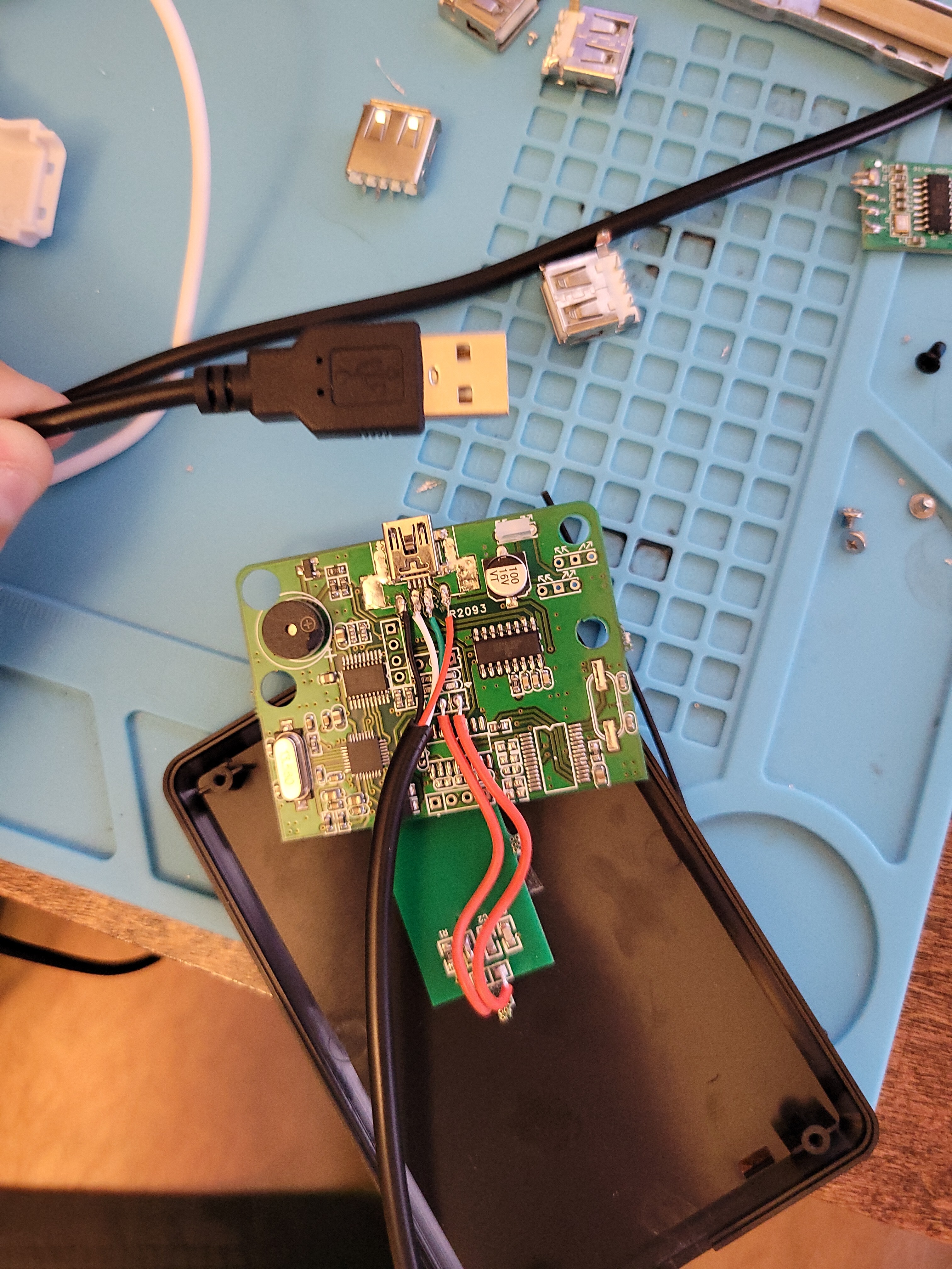
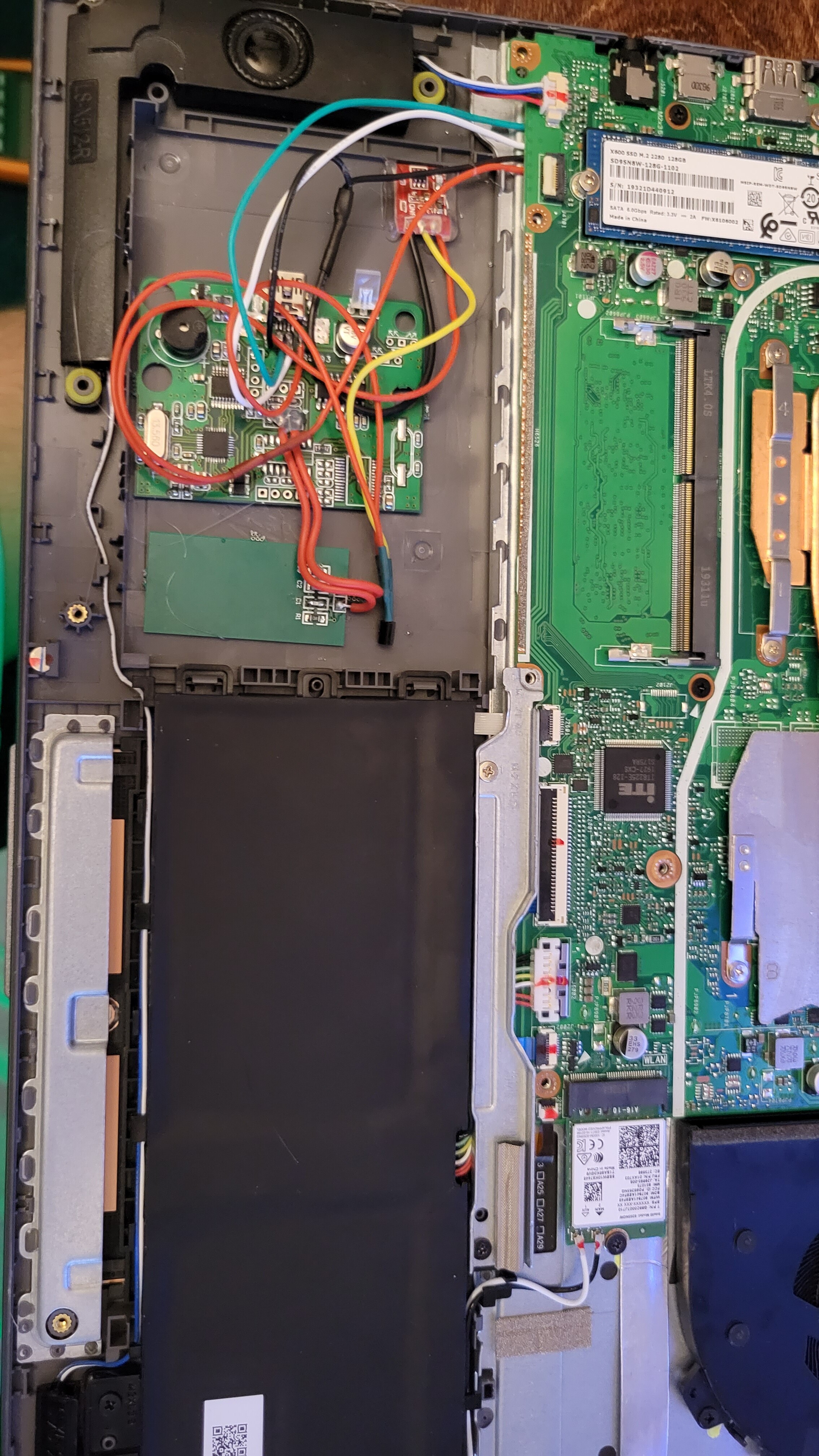
was a USB hub that I put in there so I could “add” extra ports. At this point ended up being a pita so I removed it. Currently, just cut off the end of the USB mini-b and soldered the 4 wires to the back 4 pads. then plugged the other end into the pc

here is how it’s wired at the moment.

image

Using the same cable (usb mini b) still there, from another one I have works great

I think you’ve got your white and green swapped around. Order is usually VCC (red), then D- (white).

Hard to find a diagram for mini USB that doesn’t show the unused ID pin, but here:

c87ed04acebf0c26e8cef5057dafc87e

That’s also just the general USB pinout.

14d42b729cdd24e73a2fccade4fbc820

4 Likes

… wow I’m dumb

3 Likes

one thing I’d like to note for the next person that does this. Make sure you try it outside the case first lol.

Also there is no need to remove the mini-b connector on the kbr1. I think that’s what hosed me with the first one I tried. it must ground out one of the pins.

2 Likes

Everyone makes mistakes. The important question is how do you respond to them.

One of the questions I usually ask when interviewing people is to tell them about a mistake I made, and what I learned from it. Then ask them to tell me about one of their own mistakes.

In this case someone pointed out the mistake and you learned a good lesson from it.

4 Likes

Final Update.

I wish I was better at schematics or really understanding how to create one in the first place, but alas here we are.

I ended up wiring everything up using a capacitive touch sensor and a transistor.

4 wires from the back of the PC USB port. I took power and ground and split them. Then connected the three grounds together kbr1, touch, and PC.

Then wired the 5v from the (pc → transistor → kbr1) and (pc → touch button)
Lastly, touch button I/O to the base of the NPN transistor above.

This allows me to turn on and off the kbr1 with the touch sensor, thus allowing the use of the USB port when I’m not using the kbr1.

7 Likes

Bloody brilliant idea :bulb: