

![]()
![]()
1 Like
You KNOW what I am going to say, BUT what is your plan
More batteries, diode on the charging circuit, up the charging voltage to compensaste for diode, and just generally clean up the build. It’s the little things that I could’ve done better in hindsight.
I think I’ll keep the entire original though and mount it on my shed door.
Gonna need a solenoid that’s compatible though.
1 Like
I’m working on a similar project as far as an RFID controlled lock for my rolling tool cart, I’m using a cheap RFID cabinet lock and extending the antenna to outside the box(the box is all metal) I’ve already been able to program it to read my xEM and everything is working out so far.
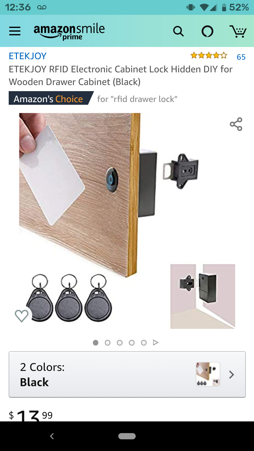
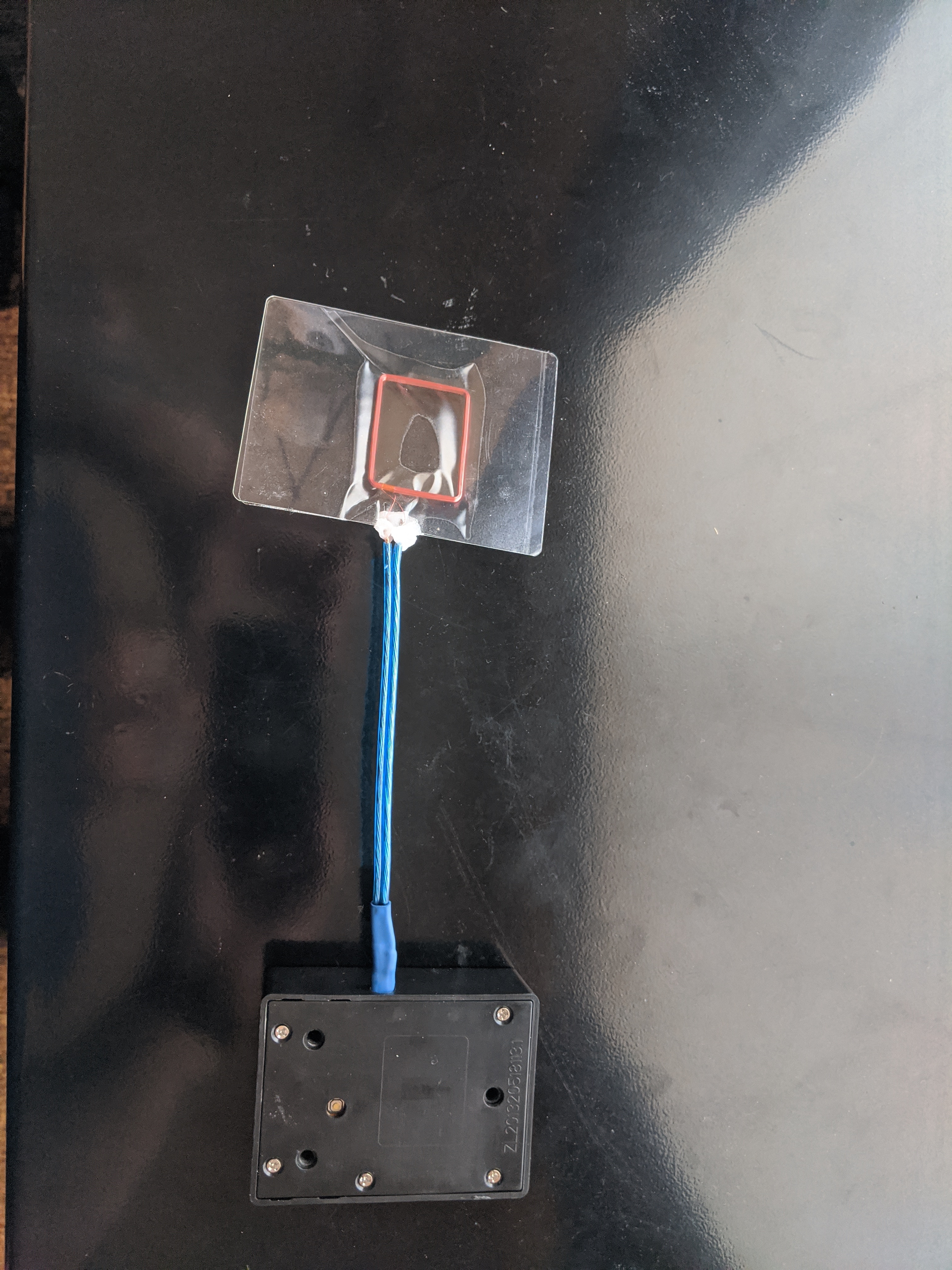
This is a proof of concept that you can extend the antenna easily
2 Likes
Dude! I’m loving it.
a coupla questions:
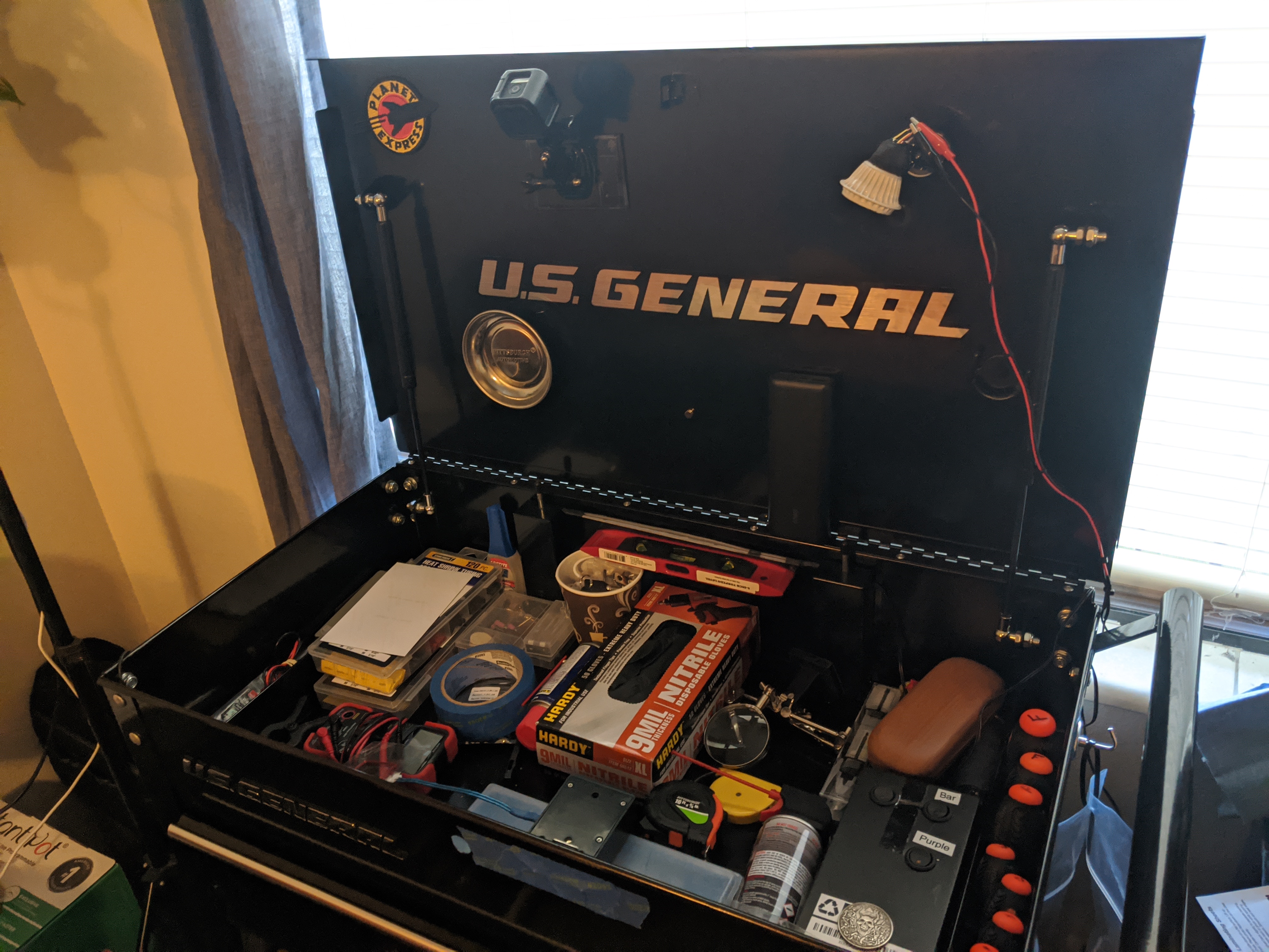
1 is that the reader installed on the front inside of the box?
2 are you ditching the manual key and / or lock entirely? It looks like you’re keeping the upper loop. Maybe that’s just so you don’t get locked out durning the build? I almost did.
Once you’re fully operational, Video is a MUST.
edit. Food for thought. There’s room for a DT sticker on either side of the GENERAL logo under the lid. I’m gonna do it.
1 Like
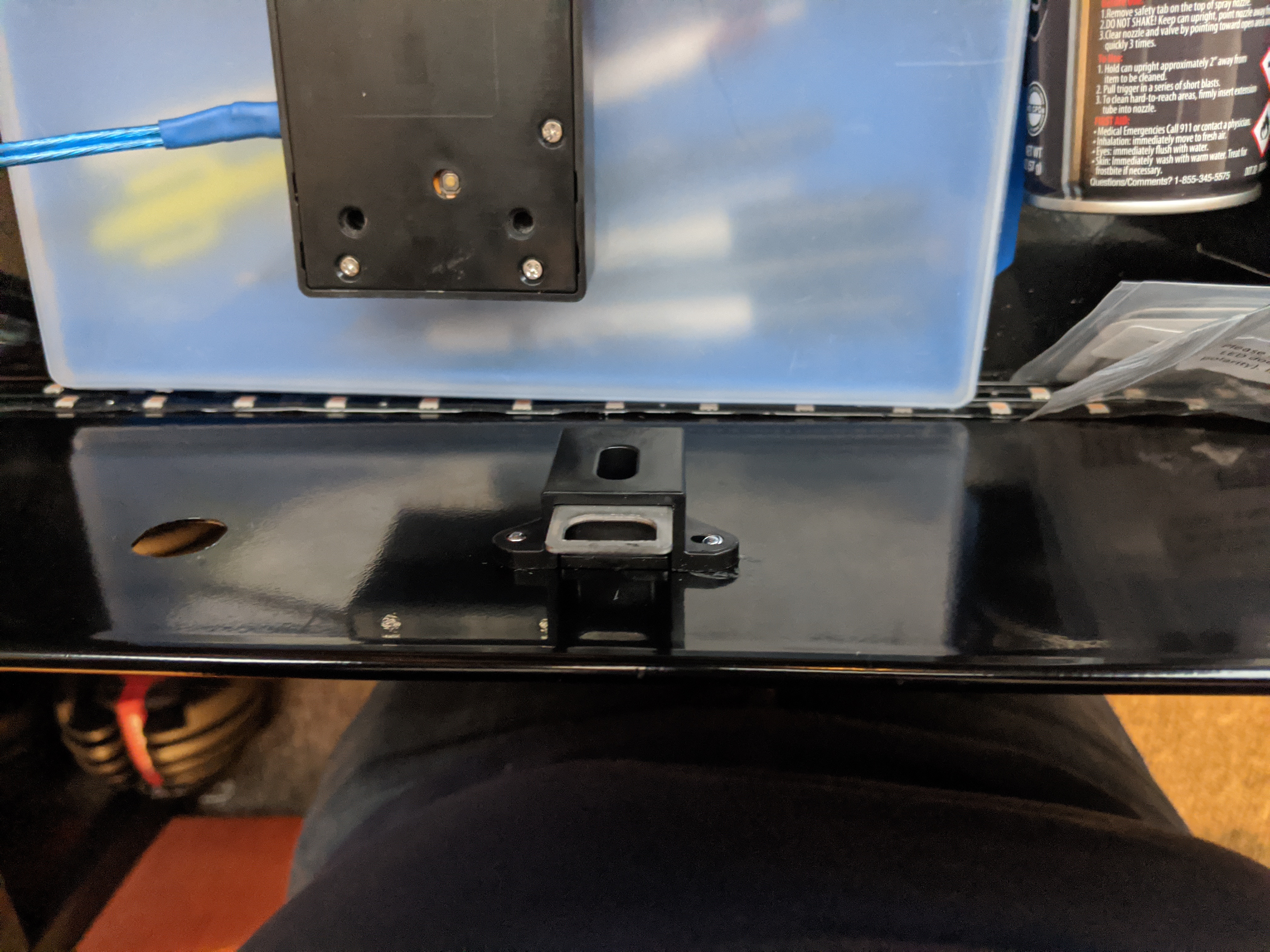
I haven’t installed the mechanism on the box yet and the antenna is going to go completely on the outside The mechanism is going to be on the inside, after I further extend the antenna. I’m also going to replace the power supply to a dedicated DC outlet to further reduce the risk of getting locked out. I might also include a back door switch. and yes I did completely remove the original locking mechanism.
Edit- I have a logo on my removable magnetic worktop
1 Like
I don’t know how, but it really seems to increase the system performance and read range!
1 Like
Has to be magic sh*t
2 Likes
Heres my finished project peeps
7 Likes

2 Likes
Been awhile, but I’m back on it.
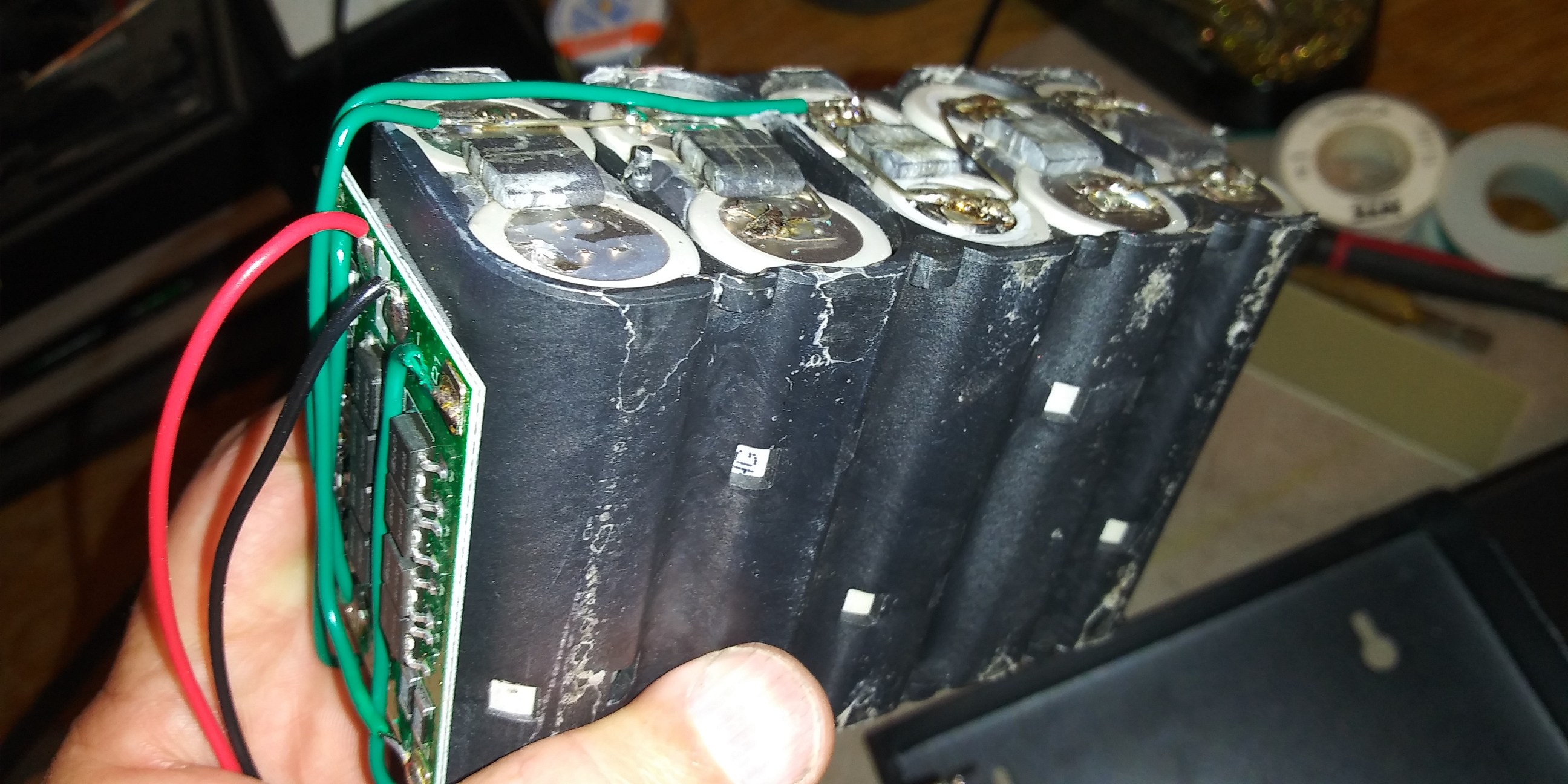
Spent a coupla hours today rebuilding a Milwaukie 20V drill battery. It was 5s2p for a total of 10 cells. Now it’s 3s3p with one extra cell that I had to put back in to make the holder work. Added a BMS and it looks good to go.
Also got the new box out and put holes, grommets, and the DC power jack in it.
Oddly enough, I can’t find a tube of silicone that I need to mount the battery pack.
For want of a nail, right?
The real progress was finding all the random bits that I’d gotten scattered across my kingdom. Progress soon.
Oh, and I ordered that capacitive touch sensor that Satur9 mentioned awhile back. The way everything works, you need your hand on the handle while scanning so that you can open it. The handle is bare aluminum. Should work great. Between the capacitive touch, and the bigger battery pack, I might be able to stretch my up time into months not weeks.
3 Likes
Parts came in. I’m building a board to house two relays, the capacitive touch module, and assorted little stuff.
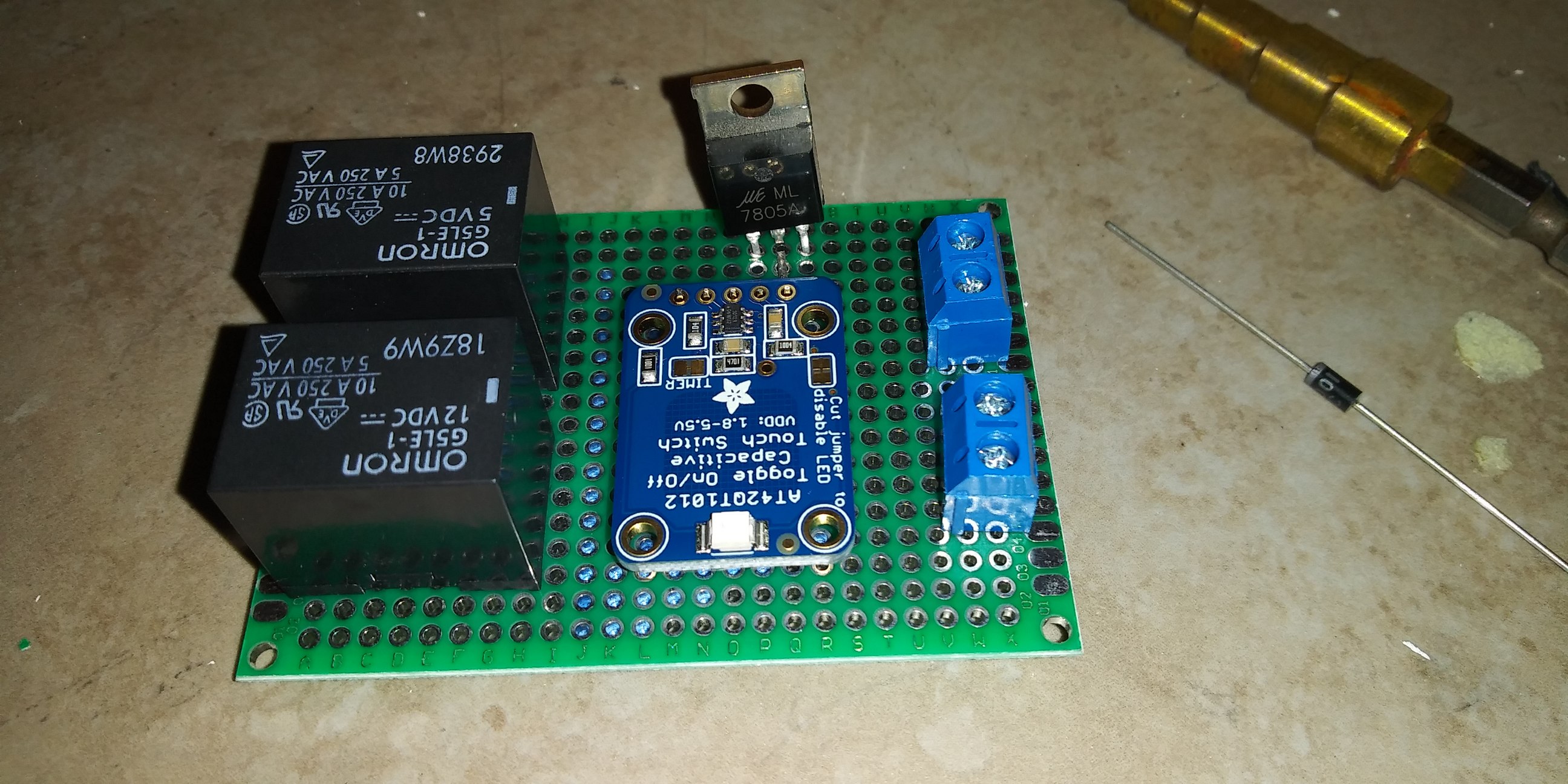
That capacitve touch board is cool. They make two different modules that are nearly identical, one momentary, the other toggles between on / off every time it’s touched. I need the momentary. Guess what? I ordered the other one. Dammit.
Ordered the right part, now I gotta wait some more. Will probably finish soldering up everything else, but taking my time as it’s kinda packed.
Also, Battery pack.
3 Likes
Need a sanity check. @Satur9 @Devilclarke
Board on the left is incomplete. It will have the touch sensor output go to a PN2222a transitor base, through a 330 ohm resistor. The collector will be 12V and the emitter will be wired to provide power to the xAC and (through the xAC) the coil of the relay.
If that checks out:
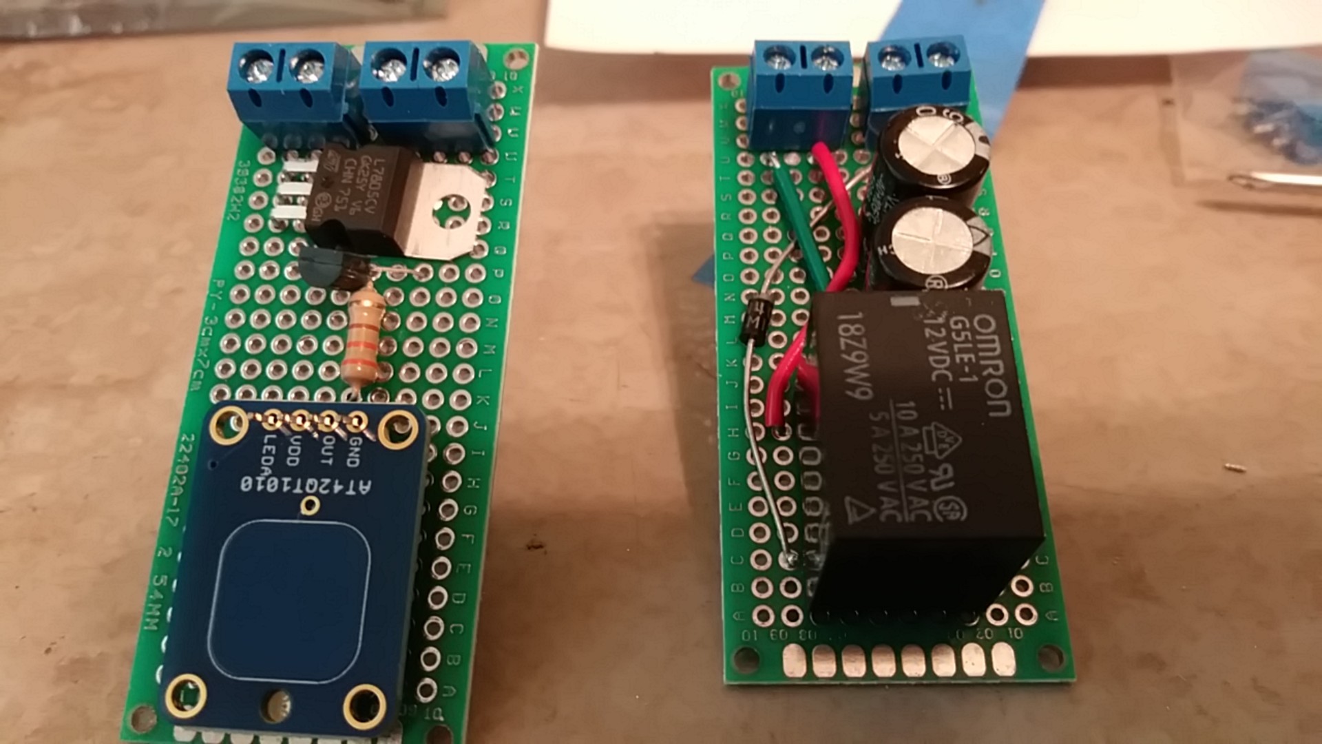
The two boards will be stacked with standoffs in order to conserve real estate inside the box.
Starting to come together.
So hold you finger here and scan looks good to me.
Cool, was just really iffy on the resistor.
And…
I put the diode in the wrong spot on the other board.
![]()
1 Like
Haha, happens to the best of us. You may find you need something higher than the 330ohm. Its just V/I*R to make sure you hit the right base current and not blow it up.
Pretty sure you need a voltage divider on the gate of the P2N2222

In addition to limiting the current IB to 50mA, you also need to limit the voltage VBE to less than 2v. The cap touch sensor puts out more than that
I assumed the use of the pn2222 was because odaily was running the touch sensor at 1.8v
Wait thats the saturation, they explicitly show using 16v on the base with a 1k.
Isnt the saturation the point of full on.


Dammit. I just soldered everything except the touch sensor.
Oh, well.
So, current IB to < 50ma
and
voltage VBE to < 2v
Riddle me this, Batman.
Can the first resistor in the voltage divider handle both the current and 1/2 half of voltage divider.
I’m wondering if I can do this with just 2 resistors.
so…
resistance for current is 5v / .050A = 100 ohms.
Use 100 ohms for resistor1 in a voltage divider, then to get the voltage down to 2v, the second resistor would be 80 ohms?
That’s right at the edge of 2V and 50ma, so I should probably recalc a little lower.
I get R1 at 130 ohms to be current of 38.5ma
With a R2 of 75 ohms, the voltage would be 1.829
Them’s some tiny little resistors. Smallest I have is 100 or 150 ohms.
DevilClarke beat me to post. Gonna sit back now and learn something.