Magic Tool Box Project

This is really more of a hardware thing, with some of my random thoughts strewn throughout, but I wanted to present this as an idea of what an implant can be good for. Fair warning, gonna be lenghthy. My original use for an implant was to have a keyless toolbox. The project got started, then had to back burner for a bit. Let me catch you up, then I’ll show some progress.

Finding a candidate tool box to modify, and picking a mechanism to install into it, was tough. Most all boxes either use a rotating rod behind the lock that runs to the back of the box to move a bar with hooks, that grabs each individual drawer, or they use a hook and catch / loop right at the front of the box. My initial requirements were that it be both keyed (manual) and electrically controlled.

While I could have worked with the rotating rod in an electrical only setup, the dual purpose really killed that one off. There just isn’t a practical mechanism that can be easily adapted into this type of lock / rod.

Side note, while typing that out, I did think of a way, but it’d require scanning your chip for EVERY time you wanted to open a drawer. Little bit too aggravating.

This left me looking at the other type. Most of those operate off of a top lid opening concept. But even most of those still use a rotating rod style on the drawers below. In theory I could have electrically opened the top, to get a key to open the lower drawers. But that’s kind of a buzz kill.

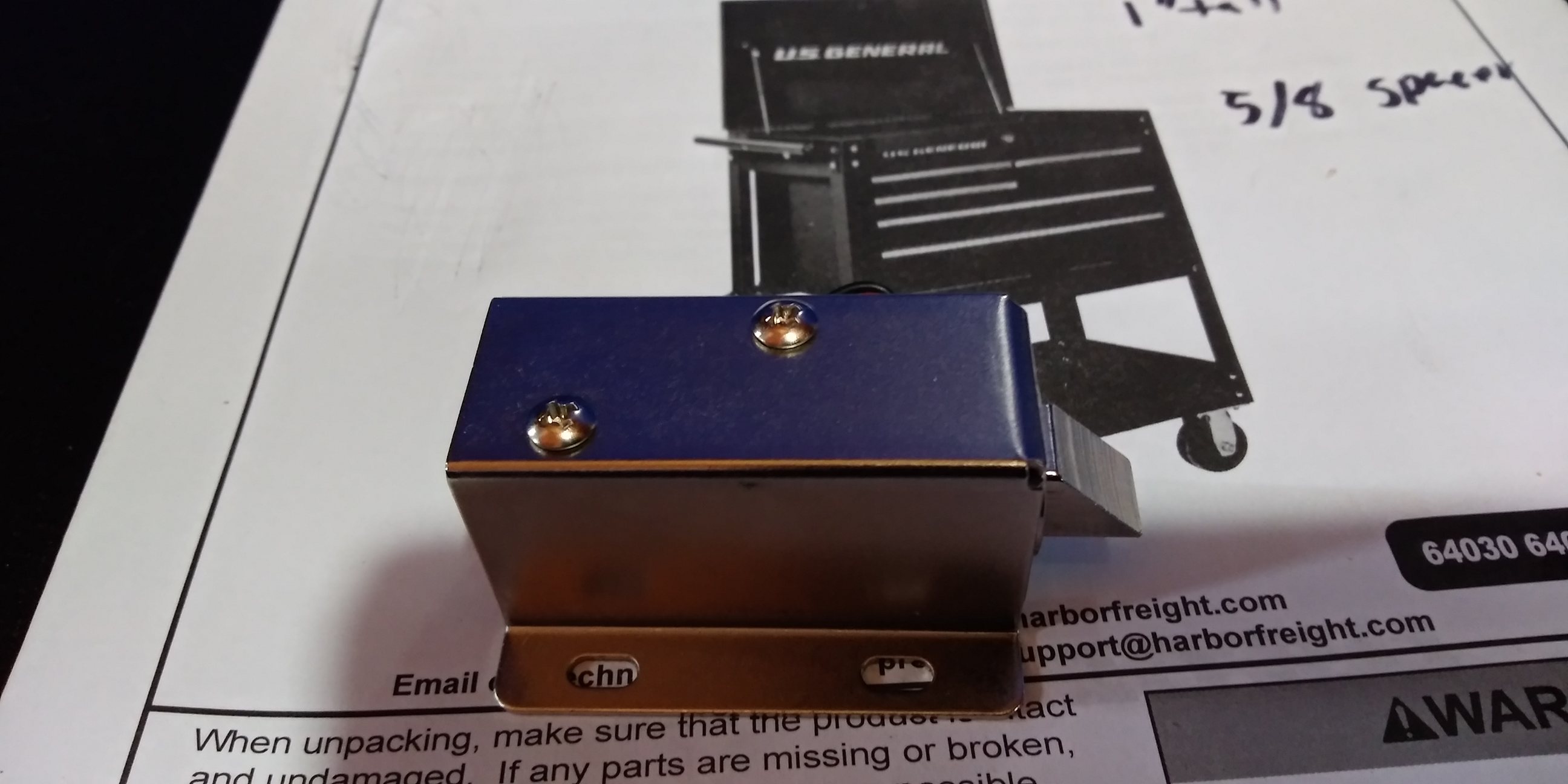
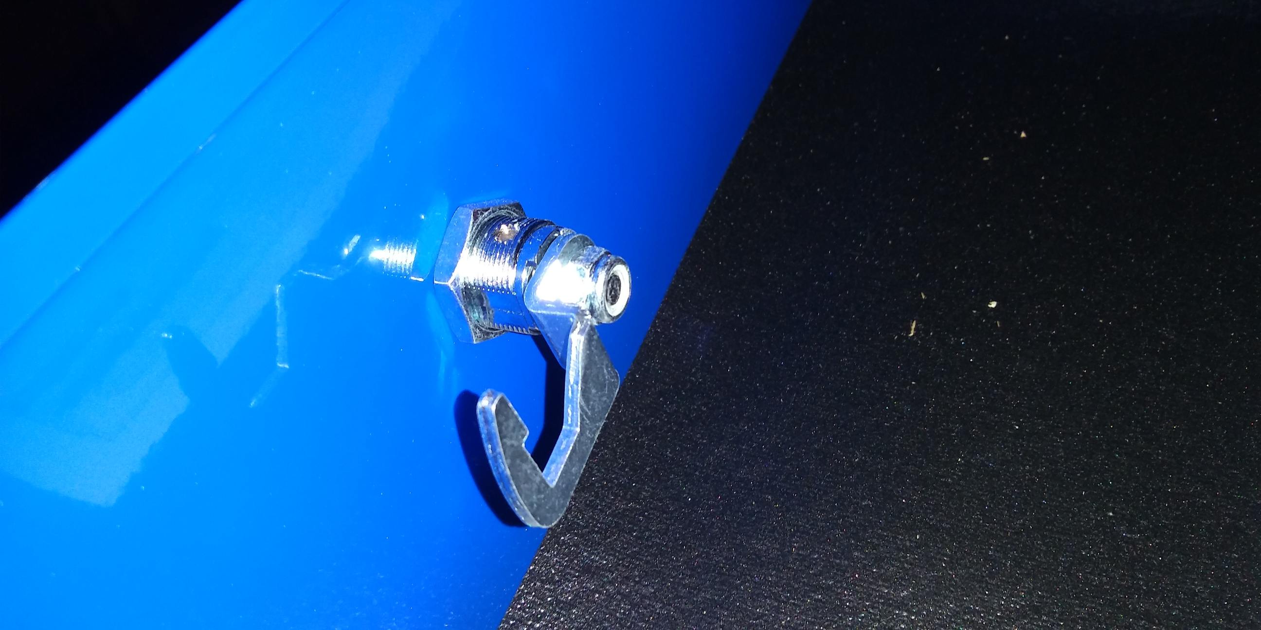
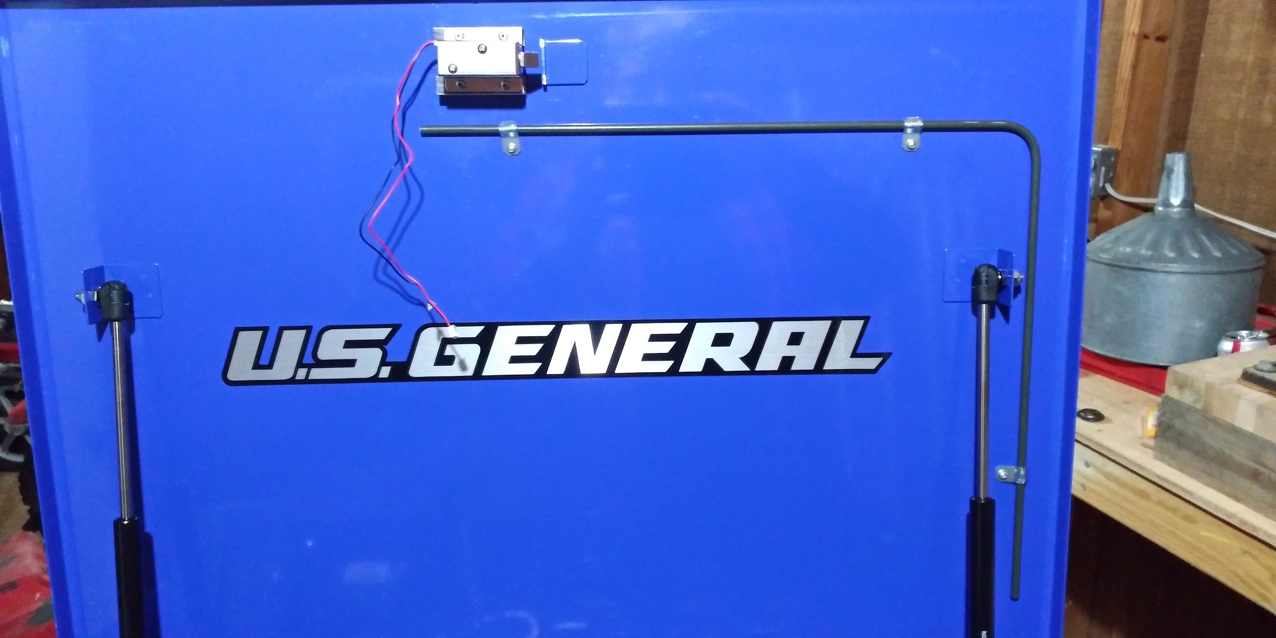
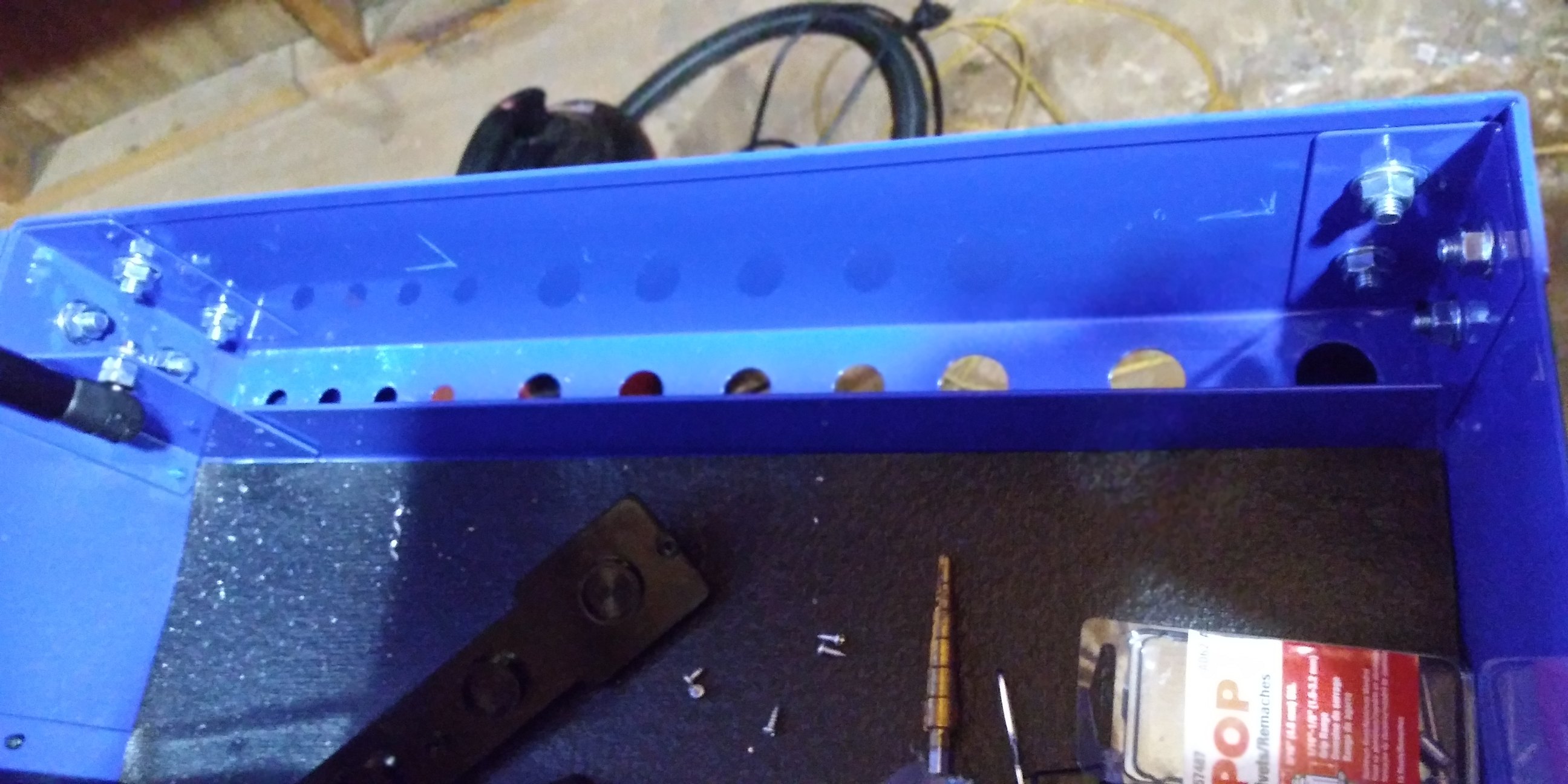
I checked a bunch of boxes until I came across the Harbor Freight tool chests. They come in 3 or 5 drawer, with a top opening lid. But most importantly, they use spring loaded lock bars that automatically retract when the lid is opened. Furthermore the lock hook and loop is out in the open with plenty of room to mod it. Bought one in color BLUE.

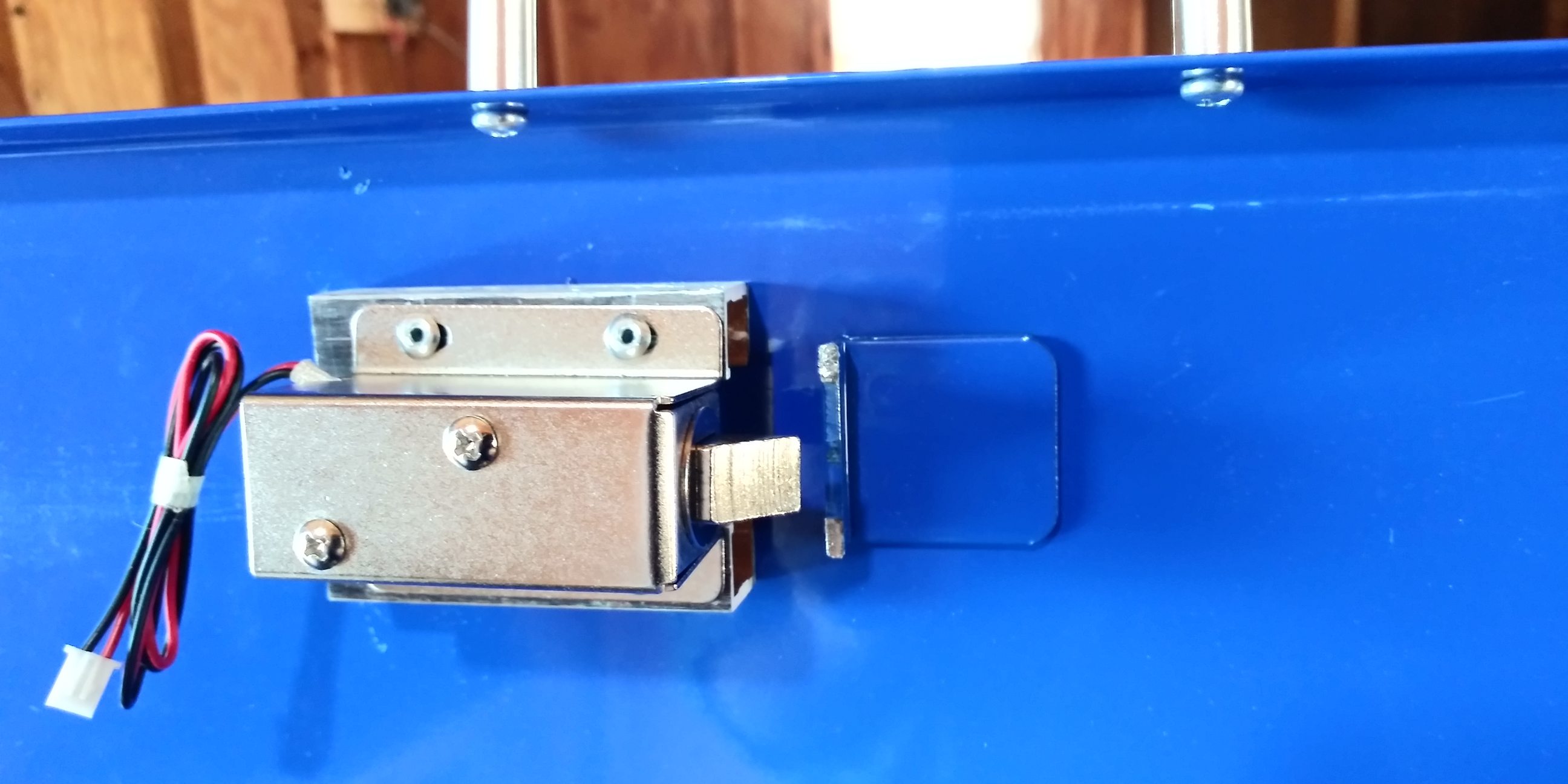
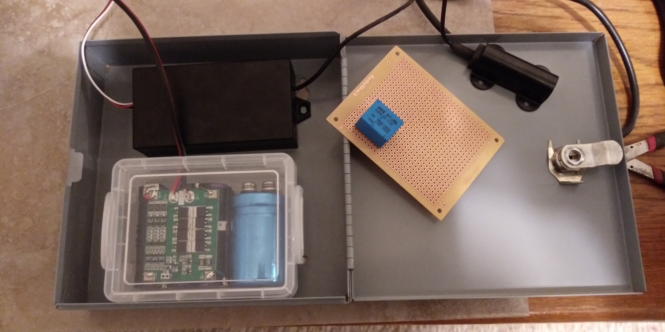
At about this time I acquired a second requirement. I needed to be able to shut the top without Manually unlocking, or Electrically retracting the mechanism. I need it to shut easily, and be locked. Easy to lock, just scan back in when you want. This got me to thinking about door latches, and how they slide up a ramped surface. Went looking and whadya know, I found a solenoid just like that at sparkfun. 12v for 9.95 plus shipping.

5 Likes

Ok, all caught up.

The box uses this hook on the lock.

and this loop on the lid…

All I really had to do, was slip a hacksaw blade through the loop and cut it off. (at least the loop portion of it)

Then I carefully (more on this later) laid out the holes for the solenoid onto the lid, and drilled them. Because the solenoid wasn’t tall enough, I also had to lay out and drill two pieces of 5/8 wide C channel aluminum to use as spacers. I then installed everything with 1/8 pop- rivets.

Now the later part…
After you measure twice, but before cutting once, Measure it again. I was off, and the latch just barely caught. I had to drill out the pop rivets, and make new spacers that shifted the solenoid over just about 1/4 inch.

Anyways, it now looks like this.

I can currently open with the manual keyed lock, and shut the lid either locked or not. As soon as I get the xEM Access Controller installed with a suitable battery and charger, I will have a magic tool box.

Will update as I continue to make progress.

5 Likes

Nice project, and thanks for sharing.
are you going to run the xEM antenna remotely and mount externally or put in a plastic “window” to read through?
Would be great to see a video when you are all finished.

1 Like

The tool chest design has a recessed area on the side, just about where you can comfortably place your hand. The sensor goes there. (theoretically) and everything else goes on the right side of the box under the lid.

Harbor Freight also sells a matching power strip. That’s gonna be installed to provide juice for recharging. Just make sure it gets plugged in once a month or so.

sounds made for it, good luck

It’s been one step forward, two steps back the whole way. I’m waiting on holiday delayed shipping for parts I need, and I just found out I have no thin gauge braided wire. Ugh…

Anywho.

I did get some automotive brake tubing bent and attached to the lid to act as a conduit.

The original plan was to put all the electronics in this area on the RH side of the box, and cover it with powerstrip (matching powder coated blue), but… ain’t gonna work. There isn’t enough width.

So Plan B is, I’m going to move everything to the recessed area I mentioned earlier. I have a metal lockable box that’s originally for storing keys or something. It fits perfectly. I should be able to mount the sensor on the lid, in the upper LH corner.

Should be plenty of room, but not too much. Just gotta wait patiently :rage: for stuff to arrive.
I might switch out that regular key for a tubular pop machine type. People are less likey to mess with those.

2 Likes

Eh tubular locks are better than wafer locks but only by a slight margin. Tubular picks are incredibly easy to come by and use. Your best bet is a proper pin/tumbler core with good pins and bitting.

Security is only as good as it’s weakest link!

2 Likes

It’s not about actual security. Heck a good screwdriver could pop the whole rig open if somebody really wanted to. A small percentage of your average co-workers might try with this lock, but most of them will pass on a tubular style.

At least that’s been my experience in the past.

@bepiswriter is bang on about the security :key: , but you are also realistic about it just being a deterrent :lock_with_ink_pen: HINT That emoji is very apt.
Regardless: Your project looks really awesome, and thanks again for sharing

Trying to get everything in that box. It’s like playing tetris. I just keep turning the pieces and hoping it all just falls into place. I removed the LED from the controller. I’ll probably put it back without the wire.

The little tupperware box holds a power pack made from a repurposed (unused) dewalt drill battery. The charge controller board came from Amazon. There’s also a capacitor in there. I just basically grabbed what fit best out of the ol’ box of spare capacitors. It’s a 2200mfd 40 volt. There’s too many variables for me to predict how long it’ll hold the relay, so I’m gonna just try it and see.

I definitely need a smaller circuit board or a different way to mount the relay. Still thinking on that one. The diode will be installed inline on the white wire or right next to relay. I want it to look decent.

Looking really tidy.
Sound’s like you are doing a good job of fitting 12 gallons of shit into a 10-gallon hat.
BUUUTTT If you want to consider squeezing one more thing in there ( actually it would only be some twin to a switch run externally) Let me explain…
If you put a momentary switch or similar trigger to power on your xEM Access Controller (even though it only draws 11mA ), you will dramatically increase the battery life saving you the need to charge / swap batteries as often; especially if your locking mechanism remains closed without power (if so that will make your wiring even easier)
EDIT I just read your earlier thread on the solenoid lock and looked it up on SparkFun, looks perfect for that option.

The only downside I can see for you is finding an ergonomic solution so that you can Trigger and swipe with one hand.
.
.
I have done a similar thing on one of my projects.

1 Like

I don’t have the math to back me up here, but I"m expecting weeks of runtime under normal usage. I could be very very wrong. I actually considered putting a solar panel on the lid. This was originally for a job that would have had multiple shifts, meaning the lights would be on all night while I was home. The indoor charge rate would be tiny, but so is the draw. What stopped that was knowing that sooner or later, people would start messing with something so obvious.

The only downside I can see for you is finding an ergonomic solution so that you can Trigger and swipe with one hand.

If I were to do that, then I’d probably put a switch on the other side of the box and two hand it. But… It occurs to me that if a person had a lifting magnet, that could be used to close a switch / contacts, so as to power the controller, then cut the power when your hand was removed. The capacitor would hold the relay powered independent of that switch (for a short time). Voila! One handed access with zero (idle) power usage.

I have done a similar thing on one of my projects.

Cool. Got pics? Can we see?

You should definitely verify with testing, but I can show you how you would do the rough calculation.

OUDH-SS-112D Relay has 320Ω coil resistance. That would make the time constant:
τ = R * C
τ = [320Ω] * [2.2F]
τ = 704 seconds

Which means it will take 704 seconds to discharge 63% and get down to 4.44V. The relay will deactivate at 9 volts, which is 25% decay. It’s all exponential and such, so I’m going to use this calculator to get a more accurate result. So it would take 202 seconds to decay below 9V, or 3m22s

1 Like

Dude, Thanks!

My relay has 400ohms resistance. So…

T=[400Ω] * [2.2F]
T= 880 Seconds
Or 14.66 Minutes. Way too long.

But I should be able to work backwards, right?

Say I want 3 seconds.
[3s] = [400Ω] * [xF]
[3s] / [400Ω] = [xF]
.0075 = [xF}
Soo… .0075F
Or 7.5mfd or 7500uf

I tried plugging the following values into the calculator.
12V initial charge
.6v (Drop out voltage)
7500uf

I get a time of 0.
Clearly I missed something here.

Edit* Ooops. Forgot the resistance of 400Ω, Which makes time 8.9s
2500uf gets me 2.99s

1 Like

Haha, I knew you would ask, I actually put it in this thread ( abridged version ) but deleted it so I didn’t derail this project Thread of yours.

Sample

So my daughter has a sleepout on our property to which I have mounted a pressure pad under the doormat; when stepped on, it powers the RFID Reader (DT Access Controller), which, when swiped *unlocks the door.
*( I have kinda paraphrased this part of the system for brevity and clarity ) There is a bunch more to it, but it is RFID unrelated, I am in the middle of a rebuild of the whole system, I am learning some new stuff (pneumatics) as I go and waiting on parts ( Mostly using Aliexpress so have to wait 3-6 weeks every time I order the wrong thing or forget to order a part )
BUT
I WILL put together something in the projects section when V2.0 is finished.
I did discuss a little of the earlier version in @bepiswriter thread HERE

O.k. I’ll keep an eye out for it when you finish up.

The battery pack / relay / capacitor / diode is fishined.

One note to anyone who tries this. That clear plastic used to make all sorts of storage containers absolutely repels glue. You can let super glue dry on it, then just pick up the solid blob right off the plastic. But… Hot glue guns work great on it. Kinda crazy, but there it is.

I ended up using a 2200uf capacitor. That’s just what I found close in my junk pile. The calculator Satur9 provided (thanks again!) shows a time of 2.6 seconds with this setup. Real world results times just a hair over 1.5 seconds. Were I to redo this, I’d probably grab a 4700uf capacitor. They’re a pretty common value in my pile, and should net a little bit more time.

On second thought, maybe not. The longer it hangs open, the more battery it uses.

And FWIW, the relay I used was a radioshack 275-248. Nothing special about it, I just had a couple. The diode was just something left over from a long ago project.

However, I’m now stuck. I ordered a 12.5V DC charger to use with it, but all the DC power jacks I have access to won’t fit it. I shoulda paid attention when I ordered. So the new charger and matching jack will be here Teusday. I don’t really want to mount anything in the box just yet cause I gotta drill holes to pass wires through still. Oh, well.

Finally got some time to play again. Everything is strapped into the box and working.

I added the LED back, but direct to the board, no wires.

The green and black wires that are coiled up in the upper LH corner are to attach to the solenoid.

The silver item in the same corner of the box is a power input jack for a charger. I may have to add a diode to that later. I noticed the LED on the plug in charger lights up when it’s battery connected. Don’t want it using up my precious battery life. I plan to charge it fully up, then see how long it lasts when opening it a couple times a day.

I only had it half hooked up, when I realized I had power and could register my NeXT. Spent a little time playing with it. Works well at all angles. Works REALLY well if you line up the long axis of the NeXT / attenna coil.

Speaking of which, I think I’m goiing to mount the antenna coil on magnets, so I can position it wherever I like.

For right now though, I’m gonna take the rig over to my buddy’s place and show him my chip works!!!

Having the magnets so close to the antenna coil will affect performance. Make sure you test it out before you apply any permanent adhesive.

1 Like

Sounds awesome
Looks awesome
Very tidy

Nice work :toolbox: :heavy_plus_sign: :lock: = :heavy_check_mark: