Do you have more than one transistor? If so I would try it out with 5v and 330ohm you will get ~15ma current to the base and if im reading it right thats enough to saturate the pn junction and turn it full on.
If im fundamentaly forgeting something I dont know but of i recall transistors can be used in a partial on state to limit “flow” I.e. the junction would not be saturated. I think what Satur9 quoted was the voltages that must be present as a minimum to saturate the pn junction.
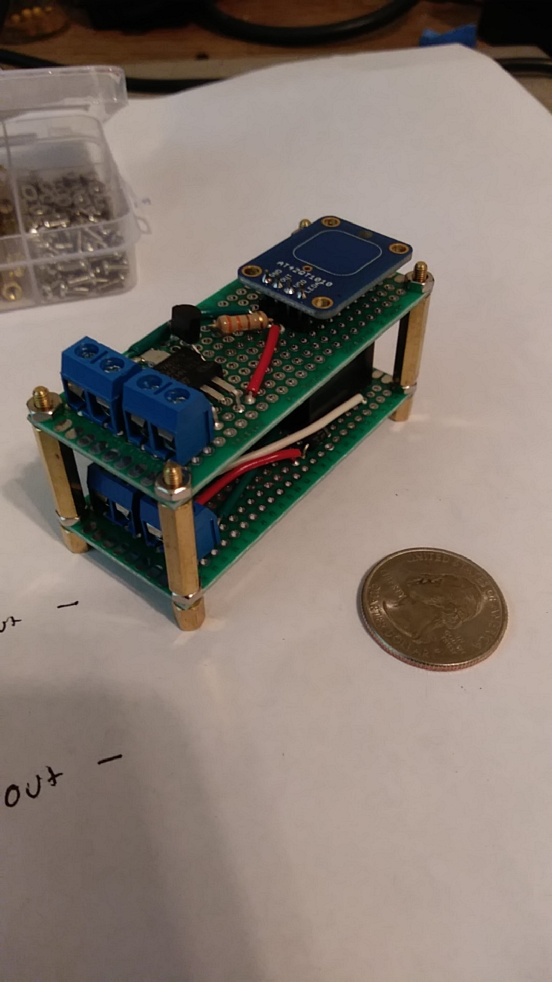
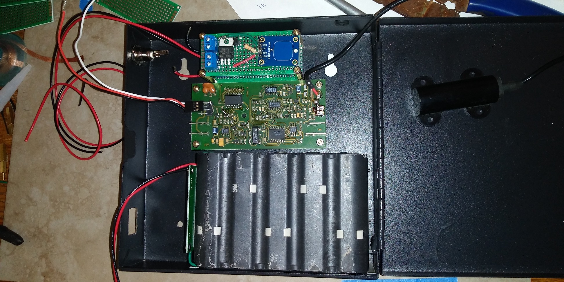
All boards hardmounted on standoffs, battery pack glued in place with black silicone. Some wiring present. One feature I needed and wanted to add is an on / off switch. The touch module runs a self calibration when it first powers up. I’ll need to install everything, kill the power, and then reset for a baseline.
I needed a single throw double pole switch so that I could isolate three items. The charging circuit, the battery pack and the power to the circuitry. But, as always I goofed. The switch I had was panel mount and I cut a square hole in the box to mount it (out of sight when finished) but I got it too hot with the soldering iron and had a terminal come out of it’s plastic holder. Not fixable. I got another coming from digikey, but it’s gonna take a few days.
After that, wiring everything up and mounting it to the tool box.
Still no power. Because of how much I had to pack in and the way it assembles, it’s gonna be fully assembled, then tested. Nothing like betting everything all at once, right?
Currently have everything in, except running wires to solenoid, wire to handle (touch), and re-attach the antenna.
I used an NPN transistor (pn2222a) in a circuit with:
12v to collector
5V (330 ohm resistor) to base (signal from touch sensor)
emitter wired to power the xAC.
(correct me if I’m wrong)
My problem; the transistor is working, but only outputting 5v or a little less. From what I can tell I made a mistake when using a NPN transitor on the high side. I should have used a PNP.
Problem 2, If I just swap out for a PNP transistor, then my input logic will be bass ackwards. IE, it’ll be on all the time, except when I try to activate it.
If I can’t sort this out shortly, I’ll have to ditch the capacitive touch and just rely on my much expanded battery capacity.
You’re right about PNP transistors going on the positive side of the load and NPN going on the negative side, but that has no affect on the logic. NPN just blocks the path to ground for the xAC. It doesn’t matter that the 12V line is live, if there’s so current pathway to ground. Circuit = circuit by definition.
Another note about BJT transistors like this one is that you usually don’t just hook up a voltage directly to them (5V in this case), you bias them with a voltage divider. The resistor in series with the base pin (R1) is there to limit the amount of current being wasted biasing the transistor. The resistor between the base pin and ground (R2) is used to set the VBE and is scaled off of R1 to make a voltage divider.
Looking at the PN2222A datasheet, the Base pin needs at least 20nA of current (IBL Base Cutoff Current) so let’s leave a healthy margin of 50nA, to guarantee activation while wasting as little power as possible. The datasheet also says the base pin only needs to experience between 0.6-1.2V (VBE Base Emitter Saturation Voltage). Let’s aim for 0.83V because it will allow more than enough current flow (~100mA from the chart), and I checked and the resistor values are convenient.
If we use a 100kΩ resistor in series (between the cap touch output and the base pin) then:
5V / 100kΩ = 50nA
If we couple that with a 20kΩ resistor between the base pin and ground (to form a voltage divider) then:
From this, and ignoring the fact that I’ve got my NPN transistor on the wrong side, it looks like the “Active” (when current is flowing from collector to emmiter) state of the transistor is +5v for NPN and 0v for PNP. This is what I meant about the logic being backwards.
It looks to me that if I just dropped a PNP in there, that it would power the xAC whenever the touch sensor was not being touched, which sucketh mightily.
From my ignorant viewpoint, to switch from NPN to PNP, I’d need a not gate between the touch sensor and the transistor to change it to the opposite voltage.
Once again, not arguing, just trying to make sure I understand what I think I do.
Unless I am mistaken the differences between NPN and PNP are the direction that the current flows in between the emitter and the collector, (that shouldn’t make a difference for triggering a relay) and the polarity applied to the base.
It won’t help your power usage but the capacitative touch switch you are using can be used just by swapping the transistor, and turning it round (emitter and collector swap places) then the capacitative touch switch toggles the transistor the other way round… Higher power draw when it is “off” lower when it is “on”.