Haha! Fair enough ![]()
So I have a red and black run directly from battery. Can this be of use ?
Ground can be ground from the battery or headlight, its all the same ground.
This little lines are from the relay picture I snipped from google, they are to be ignored.
A Diode was required on the xAC v1 but it is not needed on the V2 since it uses a relay for the output.
Sweet thanks. So the diagram above should be what I do? And where do I put fuse for xac power? If necessary
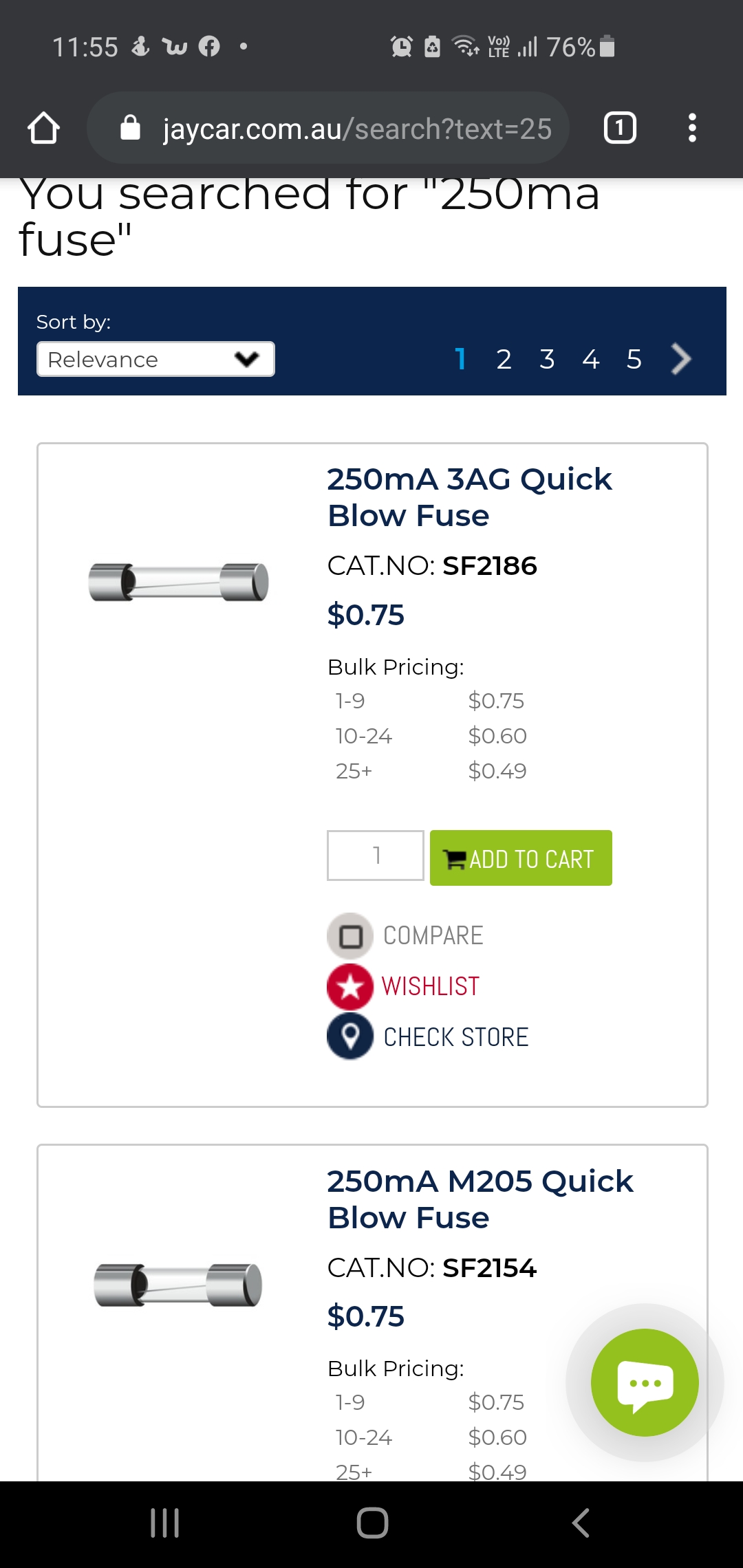
Yes, the diagram above is what you should follow. The fuse for the xAC should be on the wire that I have labeled xAC PWR. It should be a very low value fuse. A half or even a quarter amp would do.
Edit: I guess they don’t make automotive fuses that low but just find the smallest you can above 0.25 amps.
ALSO you are very welcome! I think its fun and very rewarding to use my education to help people!
Your advice is so much more helpful than anything I could find thanks!
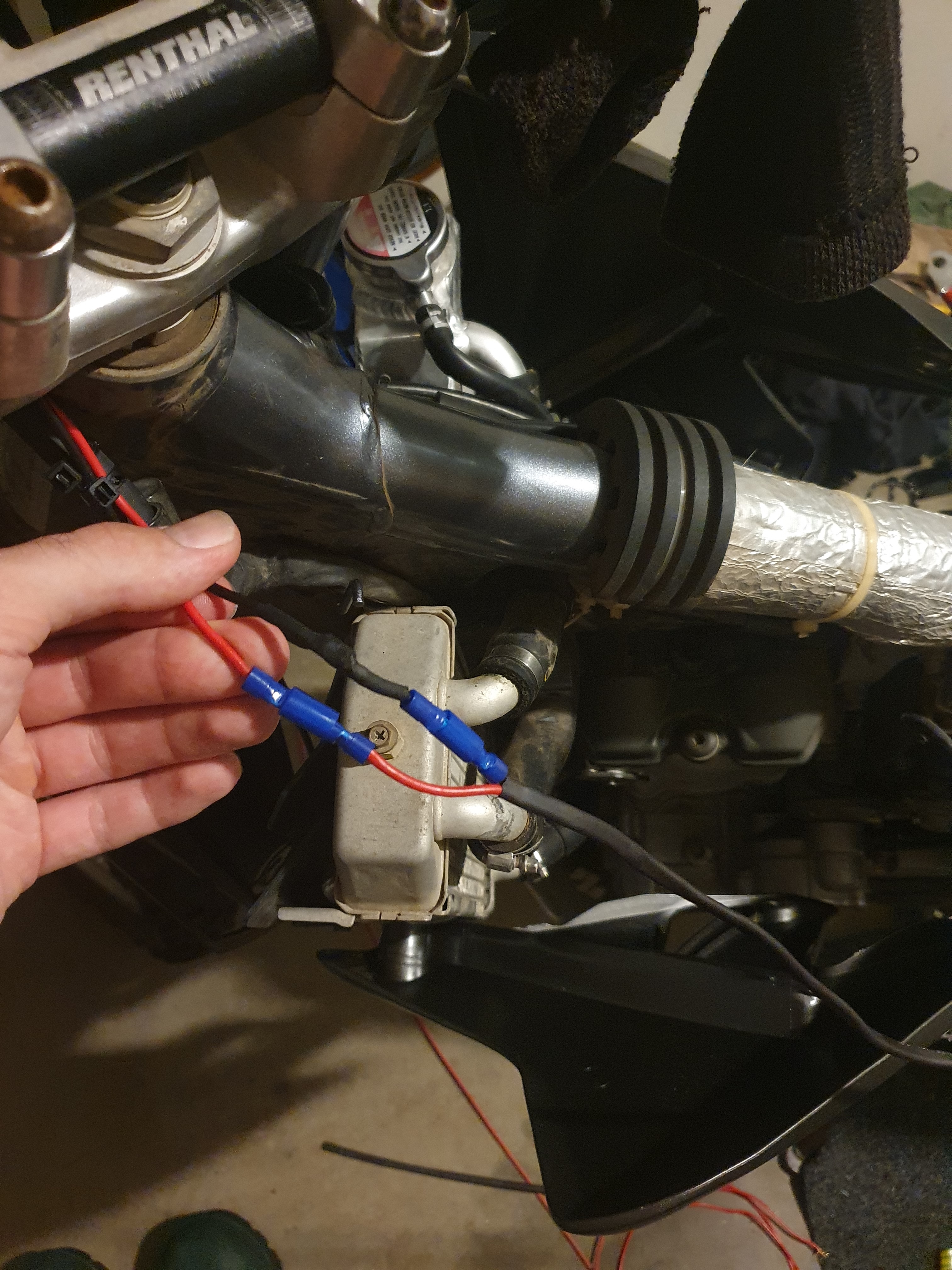
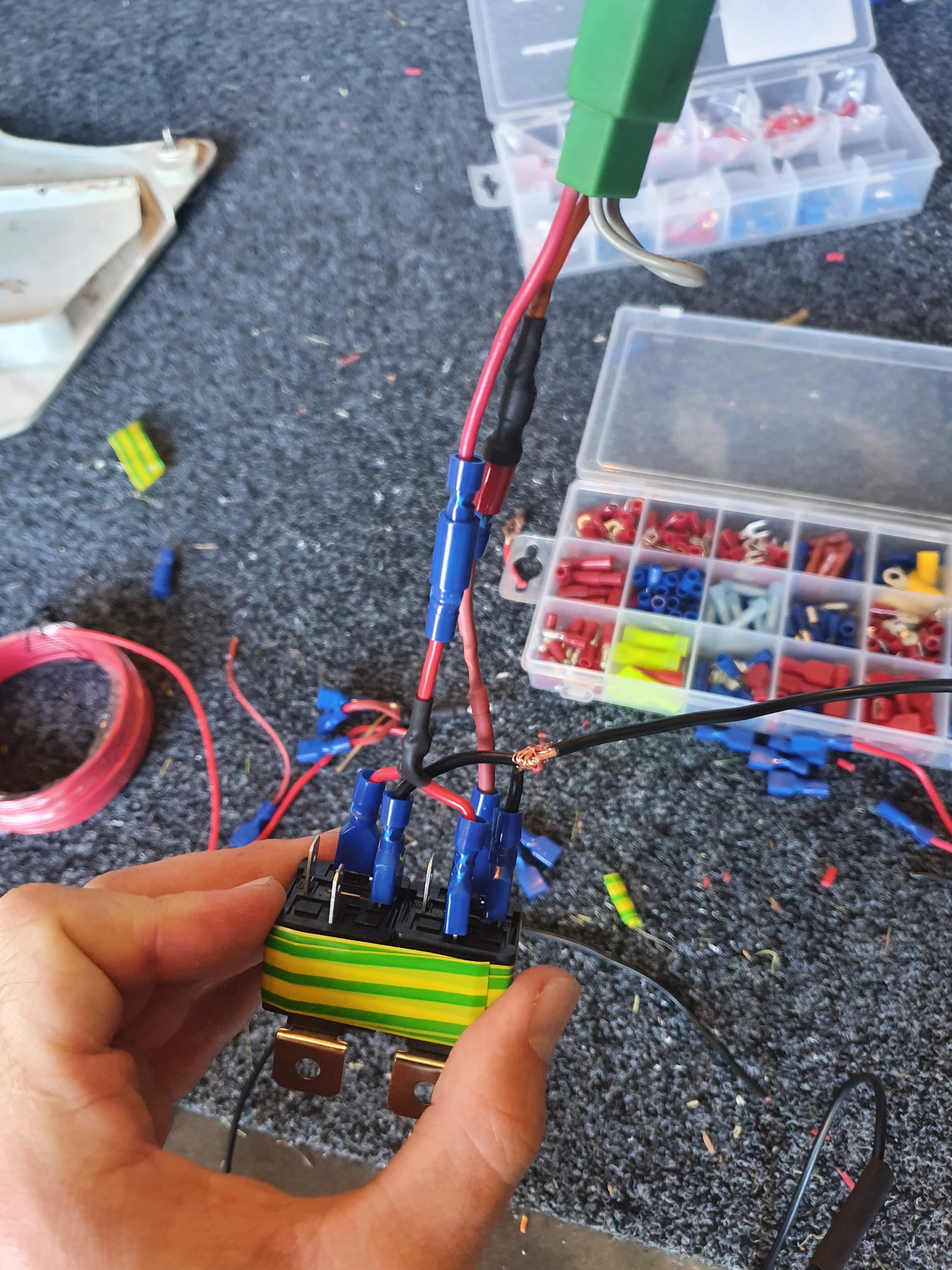
This is what I’ve done so far. Just need to add the Xac
Also one more question. How does it actually stay latched with this circuit?
Looks good! Be sure to use solder or crimp connections on your wires so you don’t wind up with a dead bike while riding!
Also don’t forget to tie the white and red from the xAC to the battery or to the red from the ignition harness!
I’m excited that you asked!
Let me draw some stuff up!
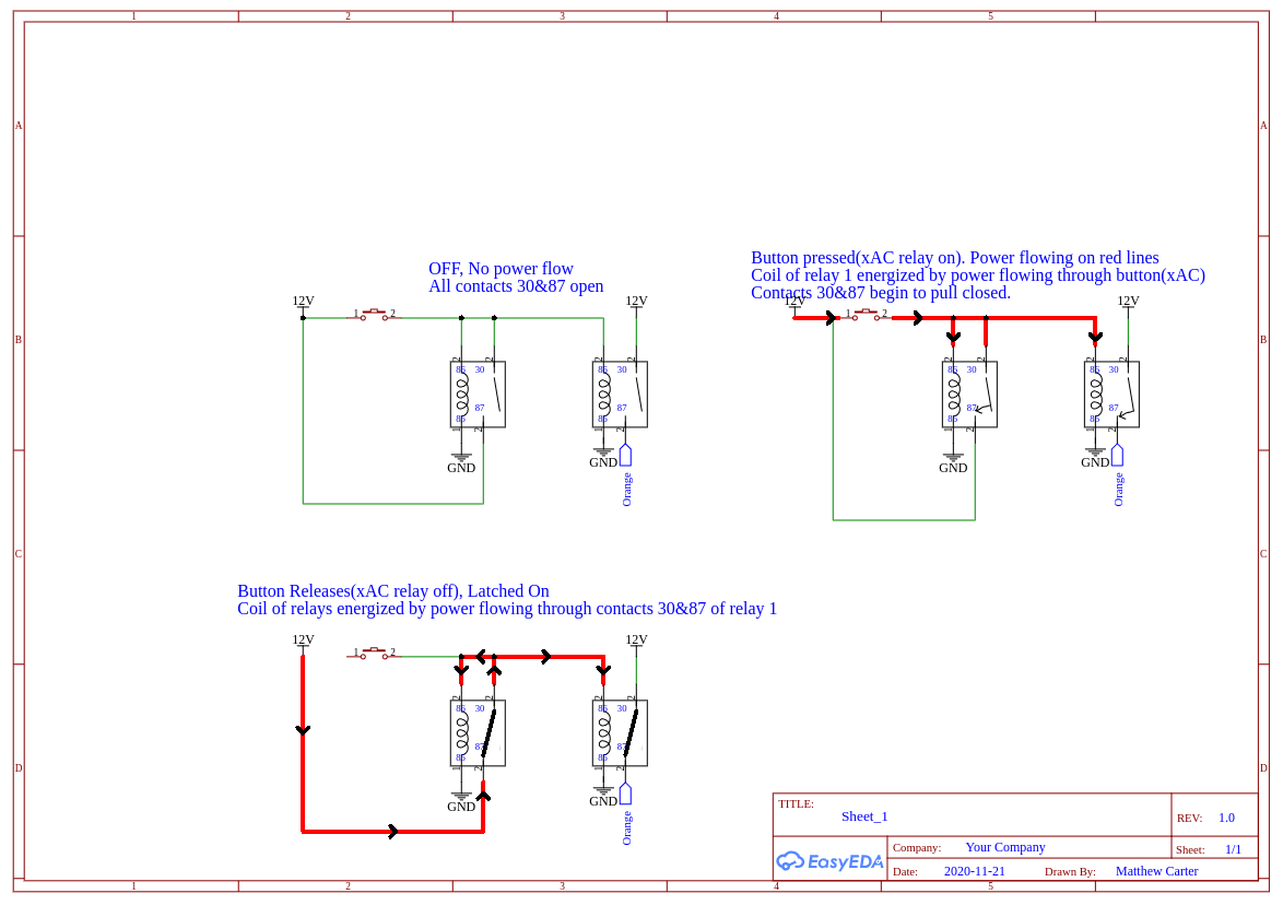
Okay the sequence of operation goes from top left, to top right, to bottom left.
In the first diagram there is no power flowing. Think of electricity as all of these angry little pixies(electrons) trying to get to GND. Since that button is not pressed, there is no good way for them to get to GND, so they stay in the battery.
As soon as the button is pressed(tag scanned and xAC relay contacts close), they see an opportunity to get to ground through the coils of both relays so they start flying. Since the pixies are running through the coil of the relays, they generate magnetic fields that actuate the contacts, connecting 30 & 87 on both relays. This creates yet another path for the pixies to get to ground on the first relay as highlighted in the third picture. And remember, pixies are fast so this all happens faster than the blink of an eye.
When the button is released the pixies stop flowing through the button (xAC relay contacts) but continue flowing through the contacts 30 & 87 of the first relay, through the coils of both relays and get to ground. This keeps that magnetic field going which keeps the relays closed to allow power to flow through contacts 30 & 87.
The only way to make the power stop flowing is to break the path, which can be broken at the power side or the ground side of the relay coils. No more flow of pixies through the coils means no more magnetic fields. The contacts then spring back open.
Electricity is some pretty cool stuff, huh!?
Wow! You really know your stuff. This has fully blown my mind but somehow makes total sense . I think I found myself a new hobbie. This is very fun.
Thank you heaps ![]()
One more question… with the yellow. Am I using the heavy wire to connect to the 30 and 86’s then attaching the little yellow wire from xac to that? That way the current flowing through has thick wire and not thin yellow wire?
Cheers again!
Here’s lesson number 2. A little more technical. Electricity follows a few laws, one is called Ohms Law. It is the relationship between voltage, current and resistance.
Voltage=Current*Resistance.
An automotive relay coil has a resistance of about 50 ohms to 200 ohms.
Since we know 2 of our variables to the equation we can rearrange it as such.
Current=Voltage/Resistance
Unless you know the exact resistance of your coil and the maximum voltage produced by the bikes electrical system, we can do analysis of the worst case. Depending on the voltage regulator on the bike you could possibly get about 14V from the stator. Well also assume worst case for the relay and say that it has a 50 ohm coil.
Current draw of a relay coil= 14/50 = 0.28A
But, if you look at the diagrams I sent explaining how the relays latch, we have 2 relays coils in parallel. I won’t get into trying to explain the parallel resistance calculation. Just Google a calculator for it. But if your 2 resistances are equal, the equivalent resistance is half of the value. So two 50 ohm coils in parallel looks like one 25 ohm coil.
Current = 14/25 which is 0.56A
With this information you can determine the wire size that you need for that circuit. Just google something along the lines of “wire gauge amp limits” and you’ll find charts with lots of information.
You are looking for the current rating. Sometimes there are 2 different ratings, Current Rating for Chassis Wiring and Currently rating for power transmission. Both of these ratings are very conservative but since what we are doing is considered chassis wiring we will use that one.
You find in the chart that the smallest wire that can handle 0.56A is 28AWG It is rated for 0.7A and is very tiny (0.32mm diameter without insulation).
If I had to take a wild guess the wiring on the xAC should be 22AWG or maybe 24AWG. Which should be more than sufficient.
So to answer your question, as long as your wire isn’t smaller than 28AWG, you’ll be fine.
Wow! Thanks heaps mcarter ![]() will hopefully finish this today
will hopefully finish this today
Thank you! I will make sure I do this . This is super exciting! Do you have any recommendations on places to start learning this sort of thing? Any online courses etc?
One of my college professors used this as his course material for my Circuit Analysis I class. Super good stuff.
I’ve also heard good things about a text book called The Art of Electronics by Paul Horowitz but haven’t had my hands on a copy yet.
Thank you for that ![]()
Also with the switch on my earth wire. What amp rating should it be?
Thanks!
Since only the access controller and the coils are connected to the switched earth you get the coil currents plus the current consumption of the xAC (Draws 60mA idle, 102mA while relay is active).
.56A for the two coils plus 102mA (.102A) equals 0.662A so anything rated over that will be good .