I’ll be happy to give you my project files when I’m done. That way you won’t lose any time and can pick it right up
2 Likes
Alright, So i made a fuckup somewhere.
I think when i did the math for the turns, trace thickness, and spacing i did it for a 30pf capacitor. Because i checked my order and i indeed got it assembled with a 22pf cap.
I found that in replacing the 22pf cap with 30pf tuning is SIGNIFICANTLY better.
So jumping while i have the motivation i did one final tune with the proper 30pf cap. Ran a quick order for myself and one set of branded ones for Amal.
I also completed the preliminary design of a significantly smaller repeater. Did a small batch of those at just about 1" in diameter. going to see how well my math is on this one.
Timeline so far…
These orders usually take 2-3 weeks. If i get them back and the tuning is spot on @Satur9 if youll have me ill like to sit down and go over your design. Id like to do final runs in flex, but…$$$… If Satur9’s genius work is successful in FR4 ill do a quick trial run in flex. My concern is that flex pcbs use much less copper in their trace and i feel it will affect tuning. Its also really difficult for me to do a tune on an already made PCB. I am a caveman and basically scrape away at the trace, then run a lead to the new exposed copper until tuning is dead on, then update my pcb schematics to match what i setup. it isnt pretty, but it works (ish).
Anyways.
V2.1L will be here mid march.
V2.1S will start testing and tuning.
V3 will be Satur9’s contribution to smdless components with integrated parasitic capacitence
V4 will be flex.
6 Likes
Do you use a vector network analyzer to measure the tuning?
The flex PCBs are made with the same copper weights as rigid PCBs. The traces can be whatever thickness you want. The biggest difference with flex is that the PCB is thinner and has different dielectric properties, so if you have antenna windings on both top and bottom working together then they’ll produce a greater inductance.
You’ve been using that antenna calculator I published to do the initial calculations, right? It’s usually not very far off, and you can either change the tuning capacitance or do another revision of the coil from there.
1 Like
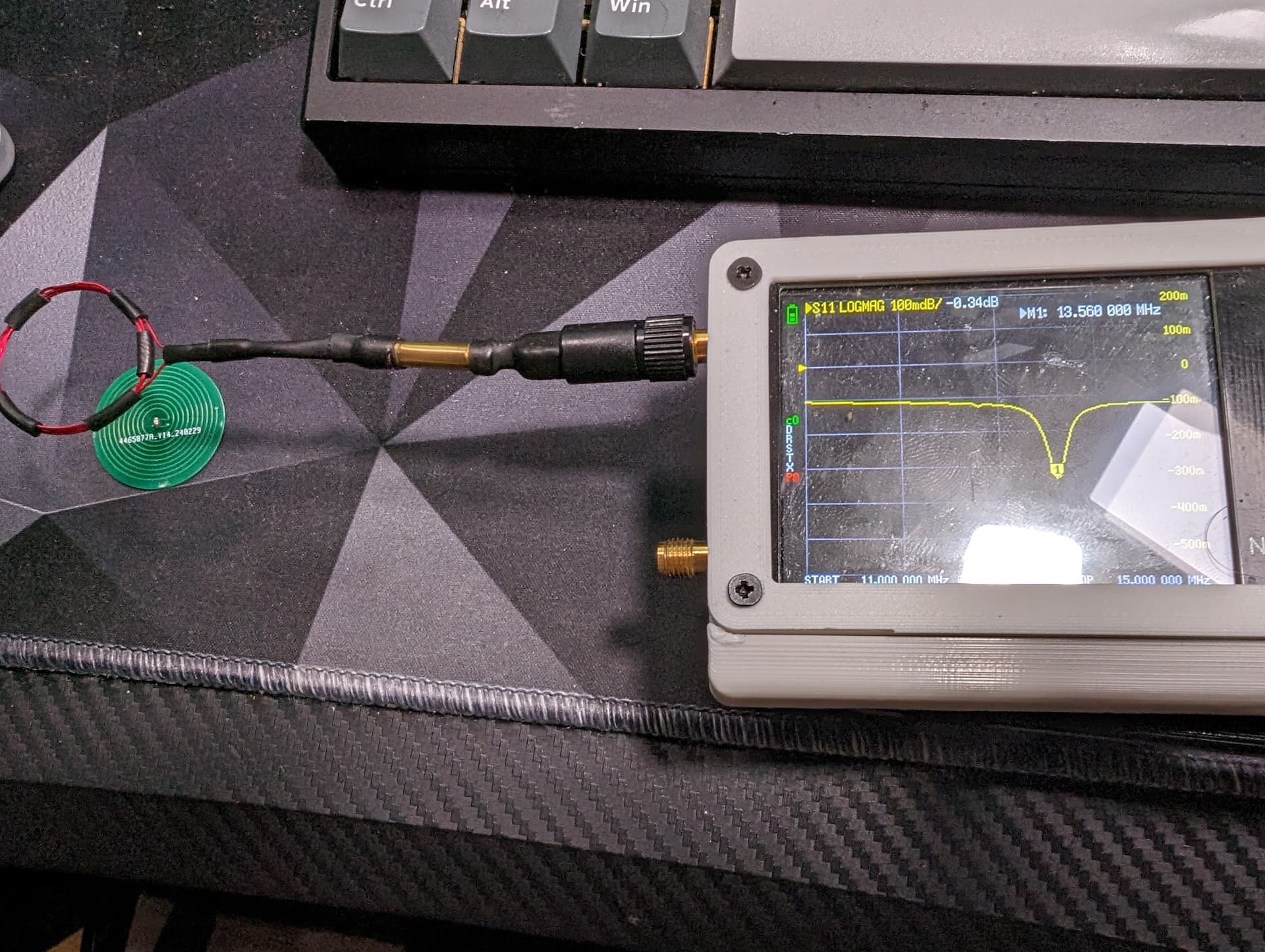
Yessir i use a nano vna to test everything. Now that i am getting into LoRa it’s been a lifesaver when i make some of the larger antennae.
I actually only have windings on the top layer. i dont use a copper layer (as i assumed that your work is all in the copper layer.
I tried. i dont know if it is because i work off of a mac but i couldnt get it to run. I used two different sites for my calculations:
You actually gave me the 2nd one which helped a lot in understanding how these work.
1 Like
Ah yeah the batch file i wrote to run the Java won’t run on Mac. You’d need to run it directly from like terminal or something. Not sure how that works but maybe a Mac guru could help. It’s probably very similar to Linux.
That calculator is probably fine honestly. If we want to use copper plates for capacitance unfortunately you’ll need to put turns on both the top and bottom to maximize the empty area in the center.
I am really familiar in terminal but i wasnt able to get it running. Probably because i dont grasp how to call java packages. but i spent about an hour on it before i just looked for Online calculators. I had about a dozen great windows VM’s but the new mac studio’s are ARM based and neither Vmware or Virtualbox allowed me to run x86 VM’s on ARM processors.
It should be fine to duplicate the coil design on the bottom layer. Since id basicaly be terminating the endpoints of the antenna into the copper layer i wouldnt need the via’s anymore. Which is the only reason it currently is on one side.
Well it will require a significant redesign since doubling the amount of turns will change the Inductance significantly, and the point is to increase the center hole size to fit plates in there so keeping it as it is won’t accomplish that. Also having the turns closer to the edges increases the coupling factor with larger reader antennas, so you’ll get better performance then if you had a chonky antenna basically covering one entire side of the PCB.
This more nuanced stuff is why I wanted to get in a conversation with you about it earlier in the design process. Simply tuning an LC Tank circuit properly is often not enough, there’s a constellation of other considerations like coupling factors, impedance, and Q-factor that are not that complex to understand but only if you have somebody run you through it. That’s why people consider antenna design the black magic of electronics, it’s a pretty specialized field that’s not intuitive even with all the math on hand.
1 Like
interesting. Alright that gives some background to the thought to it. I must have completely misunderstood the concept.
This couldnt be more accurate. What is worse is there isnt a lot of open discussions available to as easily get ahold of, and next to no information on youtube.
Until you get into other antenna design outside of PCB. LoRa and HAM’s have TONS of information regarding antenna design, structure, bends, material etc to the point it is almost overwhelming. But as far as printed circuits its hard to even find base footprints other than a handful of datasheets.
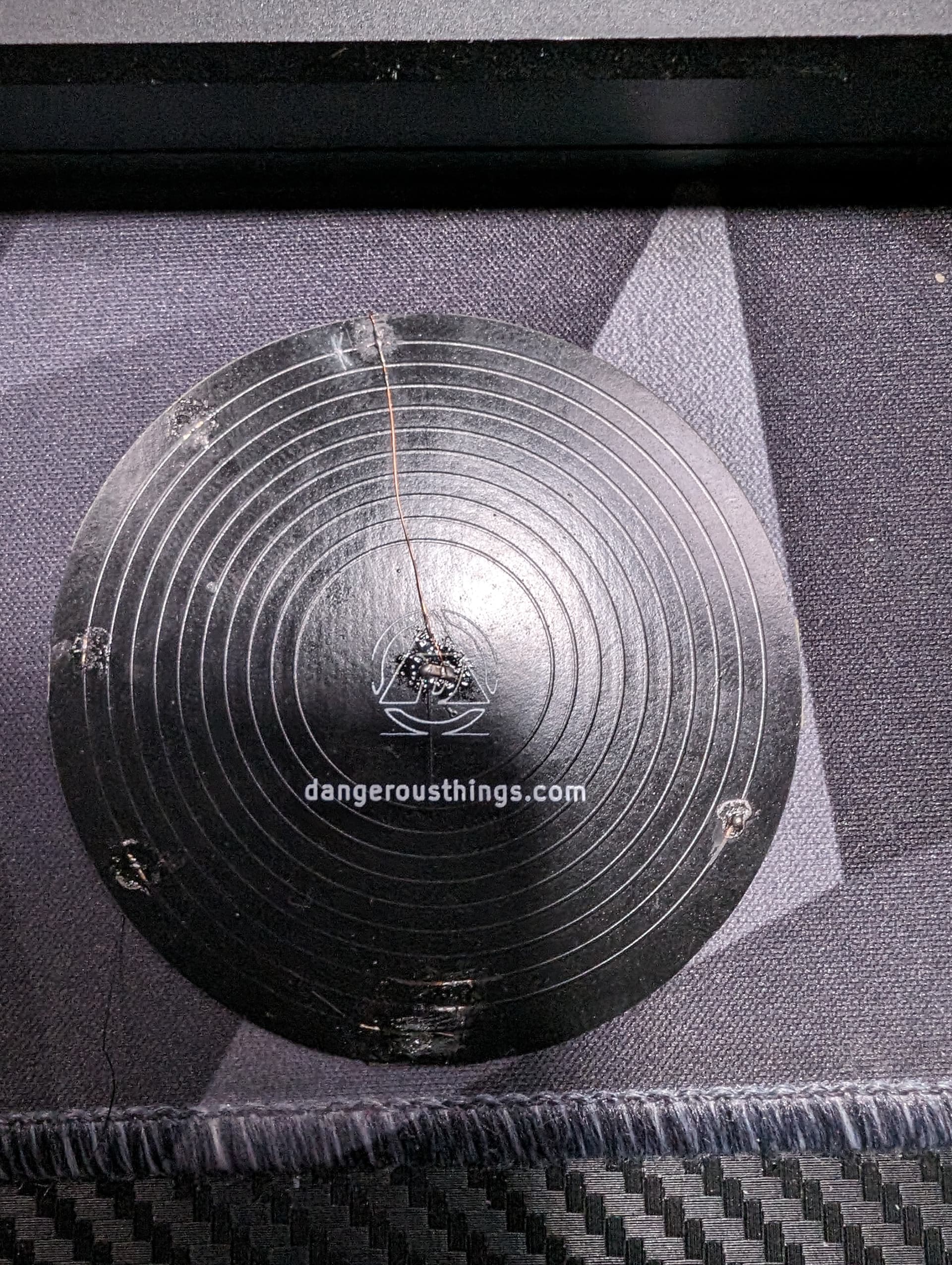
Progress Update.
V2.1 Units came in and the tuning is satisfactory enough for me to put a fork in it.
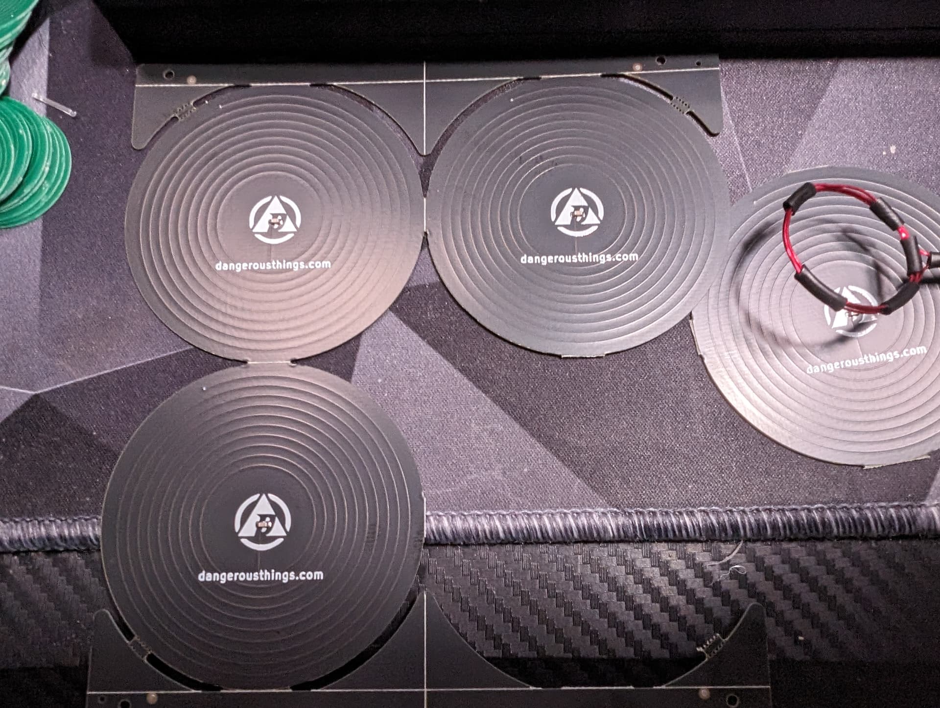
These will be packed up and sent out to Amal for shipping tomorrow. They are at about 13.56 Exactly but i am also noticing a +/- .300 variance between some units. But for our use case i dont think it should affect it any. I might try one more run of these but i dont think ill change this version anymore as i start focusing on the V2.1S
Im also going to send one off to @Pilgrimsmaster for his review. I also noticed i need to start versioning these on the silkscreen so as i work on the v2.1s ill version them properly.
Testing of the v2.1s will start around this week as i get some time. Happy with the size. These are just a bit larger than the V1’s. Gonna see what i can get these to and maybe 1-2 small batch runs and ill have something worth sending out to people.
8 Likes
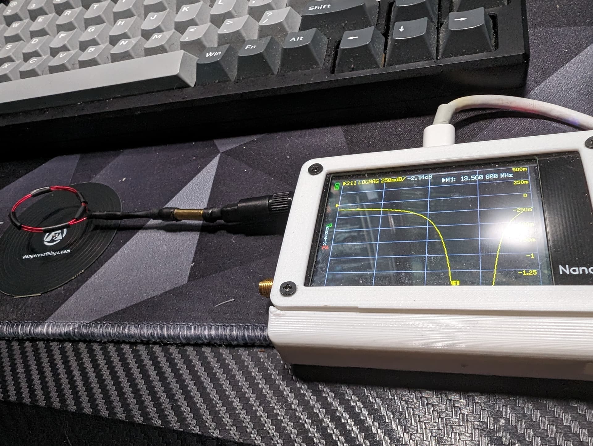
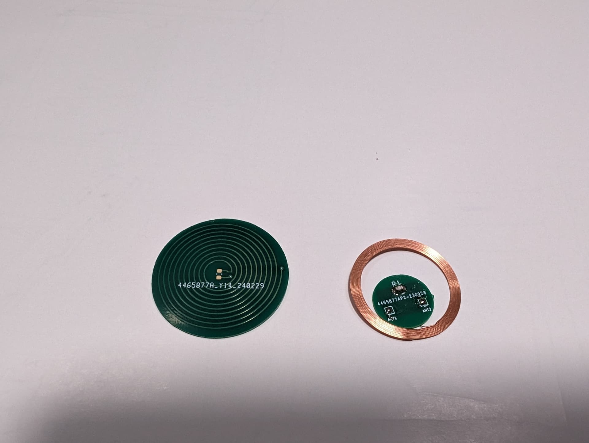
Well testing on the V2.1s went pretty quick…
Math was spot on.
So I can do a couple of things here. With this smaller design I can put an order in to get this small size made and sent out or I can just start work with Satur9 to integrate onboard resistance. If there’s interest I will do a run. I have about 20 of these prototype boards that will be up for grabs.
But I’m pretty happy with this. Couple prototypes are heading out to amal and pilgrim with the same shipment.
8 Likes
Nice! Congrats on V2.
I would be interested in buying one.
1 Like
Hot damn, that’s so cool!
onboard resistance so the smd component wouldn’t be needed at all?
That is the plan. That means we could switch to flex instead of FR4.
3 Likes
Would also make production cheap as hell since there wouldn’t be any assembly. That’d be awesome. Could sell them in packs of 10 ![]()
well Flex is still considerably more expensive than FR4, but assembly more than doubles that price. so you’re right, it cuts down on assembly, but still significantly more expensive than normal FR4.
I have a better idea of what is involved with integrated capacitence but its going to be a while before i can really integrate it as i need to understand the concepts and get the equations right. I got a good idea of how to go about it but it is going to take some trial and error on a few runs first.
1 Like
As Promised…
Since i am concluding both V1 and V2.1 as completed projects and they are standalone devices, i have released the gerber files for those items on my Github posted in the first post on this thread.
This project is licensed under CC BY-NC-SA 4.0 with Amal currently the only other entity with permission to use commercially.
You’re welcome to download the gerbers and have them made for your own uses, adaptations, etc just shoot credit back to me and id love to see what its used for!
7 Likes
Awesome work! Love me some open source projects
3 Likes
Simple ask here… but can someone do a power test to see if adding a sticker over a reader increases ambient power draw for readers? It should be miniscule if it does exist but curious.
I could later tonight. I have a few readers I could test.
2 Likes