Do you have power to the doorbell? If it does it will probably be 12v and you can probably use it to power your reader with a voltage regulator.
Yes the doorbell has power but I’m not sure how I would go about that. It would definitely look a lot nicer
1 Like
What’s the power consumption with everything put together?
About 0.5 watts
1 Like
At 5v?
Yeah “An ESP8266-12E module, for example, consumes an average of 70.5 mA when it is fully on (that is, when its WiFi modem and microcontroller are both on)” and it runs at 5V. So with that I just assumed the pn532 gets us up to 100ma at 5v so around .5 watts. It’s a guesstimation but probably not terribly off. I’d say count for 1wat to be safe.
1 Like
Well, after a lot of tinkering, reading and mistakes, I’ve finally got it all working. I can now turn all my lights on and off by scanning my Blinky! (tuya integration was a nightmare. Took me 3 hours just to get that working).
Next up, mounting it outside my house and figuring out if I can use a combination battery and solar panel or if I have to run a power source through the wall.
2 Likes
Anyone have a file for the 3D printed boxes yet? Was gonna bribe my friend to print me a few.
I did but then I changed the shape slightly. I’ll make another later today.
What program do you use to make the drawings? I’m thinking about getting a 3D printer. I used AutoCAD lkke a million years ago but I have to assume there are much better/easier options at this point.
1 Like
I use fusion360 mostly. It’s very easy to pick up and use.
1 Like
Would it be possible to extend the range or use a different NFC module with better range?
We could use this RDM6300 NFC/RFID — ESPHome if we want to stay in esp-home. But we would need an updated board design. Or we could move away from esp-home and roll our own solution with just about anything. Know of readers with really good range?
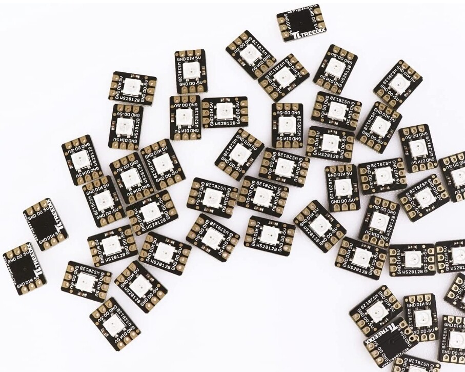
I like ESPHome since I know how to use it now but if there is another option that will easily integrate then that shouldn’t be an issue. If we need a redesign then I have a suggestion about the LED. On the board it shows we would need to solder this type of LED:

I personally have really shaky hands so soldering isn’t my strong suit and those LED’s aren’t too fun to solder. The through hole design is easier. Basically the same LED but it has already been soldered to a small board. Like this:
I’m glad you have a spot for a buzzer because I use the buzzer for the outside reader. I definitely turn them off inside though. Unfortunately I am still pretty new to all of this so I don’t know of any other readers but I am down to get a bunch of parts and try a few different versions
1 Like
This looks promising
Option 1
Looks like good range but large antenna
Option 2
This looks like the V4 reader but with an external antenna.
Option 3
V4 is better read range than V3 with no hardware or software change (cheap Amazon ones are all V3)
Option 4
125khz instead of 13.56mhz and might have esp-home limitations.
Easiest option would be to swap into option 2, but best overall will require a shopping spree and testing. I also agreed with the light being small, I used a hot air guy to melt it on before anything else was placed. You can also use the RGB headers if you don’t want the surface mount one. But you have to bridge some pins on the surface mount one and I don’t like that, so a revision should for sure be made. Once I get all these boards in I can also probably make a single board that can accept any of the options you want, just with different firmware. The main reason I used the module I did was cost, these other boards are more spendy, so I don’t want to rule out the cheap option if someone does want it.
If we want more flexibility, with thinner boards we might look into rolling our own solutions with fully pick and placed parts instead of modules.
2 Likes
I like option 1 the best since it will have the best range. Option 2 seems to have the same range as the v3. Option 3 is nice because the size is the same but if we are going to make a jump in price for the module then might as well spend a little extra and go with option 1 so range won’t be an issue. Option 4 looks good but the limitations worry me. I think for a less expensive option the first design with the v3 module will definitely work but a more expensive option with max range would be nice too. Maybe something that could use a v3, v4, or ev1 and then just different 3D files to fit the larger antenna. Designing a whole device with built in parts would be awesome. I’m sure we could come up with a solid design to make it as small as we can while also getting as much range as possible. Then some aesthetic 3D files for a case and we will really have something
1 Like
I’m definitely looking for better range. I’m currently building a car and I want to be able to unlock the doors with my implant. I’m not gonna want to be fumbling around in the rain trying to get the door to open.

8 Likes
For that you won’t use esp-home, you’ll just use a generic arduino or possibly even a purpose built chip.
On second thought if you did use an esp chip you could probably do the same thing Tesla’s do and do phone lock/unlock with a keycard backup, that’d be pretty cool haha
1 Like