Video of how things are supposed to be setup. It go over the board layout, and how to get everything simply going in homeassistant.
If you want a more in depth video I can make another going over the process of making your own code work, to name the readers, and change LED setups but that is a bit longer and more involved.
I emailed this this but haven’t gotten a reply yet. I also did order one of each readers so that I could just figure it out my self.
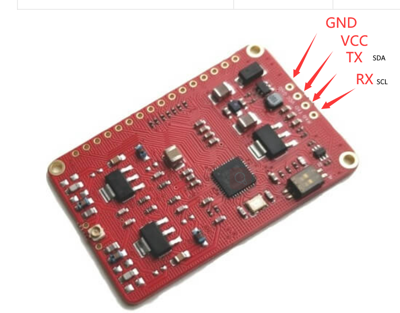
I designed an NFC reader project (you can see here GitHub - benbeezy/DTcommunityWIFIreader) I am currently using your v3 NFC reader and it works fine but some people want better read range, so I am looking at using this module PN532 NFC RFID Module w/ External Antenna - updated version - ELECHOUSE But the product page has no pinouts on the board. I assume they are on the back, is there any way I can get a picture of the back so that I can finish designing the board footprint for use in EasyEDA? I was also going to make it compatible with this reader you have PN532 NFC Evolution V1 - ELECHOUSE but I have the exact oposite issue, in that I can reader what the pins do but I don’t have a main board dimensions DWG file. So I am not sure how far apart the i2c pins are from the others. Also I am pretty sure I can read all the pinouts on this board, but a higher res picture would be awesome! All of this will be pushed into the repo and posted to the EasyEDA community library so others can design boards that interface with your boards also. Thank you and let me know if you need any more info from me, I look forward to hearing back, hopefully with better pictures and dimension files.
Yeah I figured. I should have them here in a few weeks (shipping from china) then I can finalize new boards and get the fabbed. Then tested. But on looking at the initial spec it seems like we’ll have a much better range.
The pn7150 won’t work with the current software stack. Esp-home doesn’t have a library for it. That is why I stayed away from it. The 4 options mentioned above to have working libraries for esp-home. I’d love to see a working pn7150 in esp-home, but I’m just not sure what it takes to create new libraries into it.
Perfect! I’m excited to see how it turns out! What would you think about making a LED ring part of the standard design and adjust the code so the light spins clockwise with each scan? An aesthetic piece to stand out from the other Home Assistant readers. It would be cool to put it where the antenna is but that would interfere with the range (not including the Evolution v1 since the antenna is massive). I am a huge fan of aesthetics but I understand it isn’t important so no need to alter the design for LED’s. Just a fun idea
My idea was to make it as small as possible, that’s the only reason I haven’t added a bunch of stuff to the board. That was the idea behind the extra RGB headers. That way you can put the lights wherever you want (even on top of the ESP or the reader)
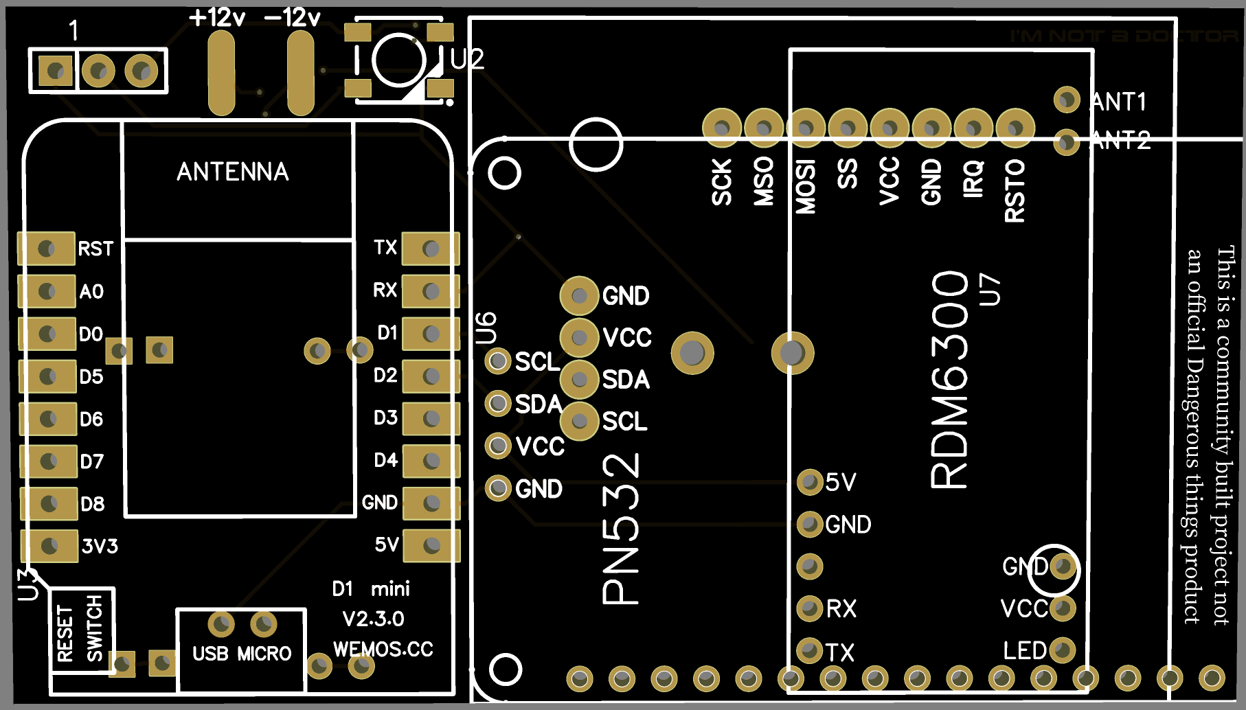
Here is the current design that works with most of the readers
You can also see that I moved the 12v system to the back of the board and moved the pads up so that it’s less likely to short (I had an issue with that)
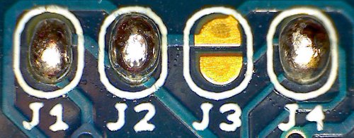
On the back here you can see the LED bypass bridge. If you want to skip the onboard LED then you short this out and use the extra RGB headers. When I added the different readers I did have to make the board slightly wider to get them all to fit. The buzzer was also moved since it was going to be under a reader regardless. So now you can mount it on the back, or run wires and put a buzzer wherever you need it.
As a side project I might also make it fit a arduino pro micro so that you can use the board as a generic USB scanner that emulates a keyboard. But that might be a branch. I’m not sure how much this board should be a “Do it all” board. An arduino keyboard scanner could be made much smaller.
Good call. I wasn’t thinking too much about size. How does one go about shorting the LED bridge? (Sorry I’m new to all of this) I like the idea of keeping this design simple and then creating a 2nd design with an arduino for the USB scanner. I’ll be happy with whatever you decide! You are doing an amazing job!