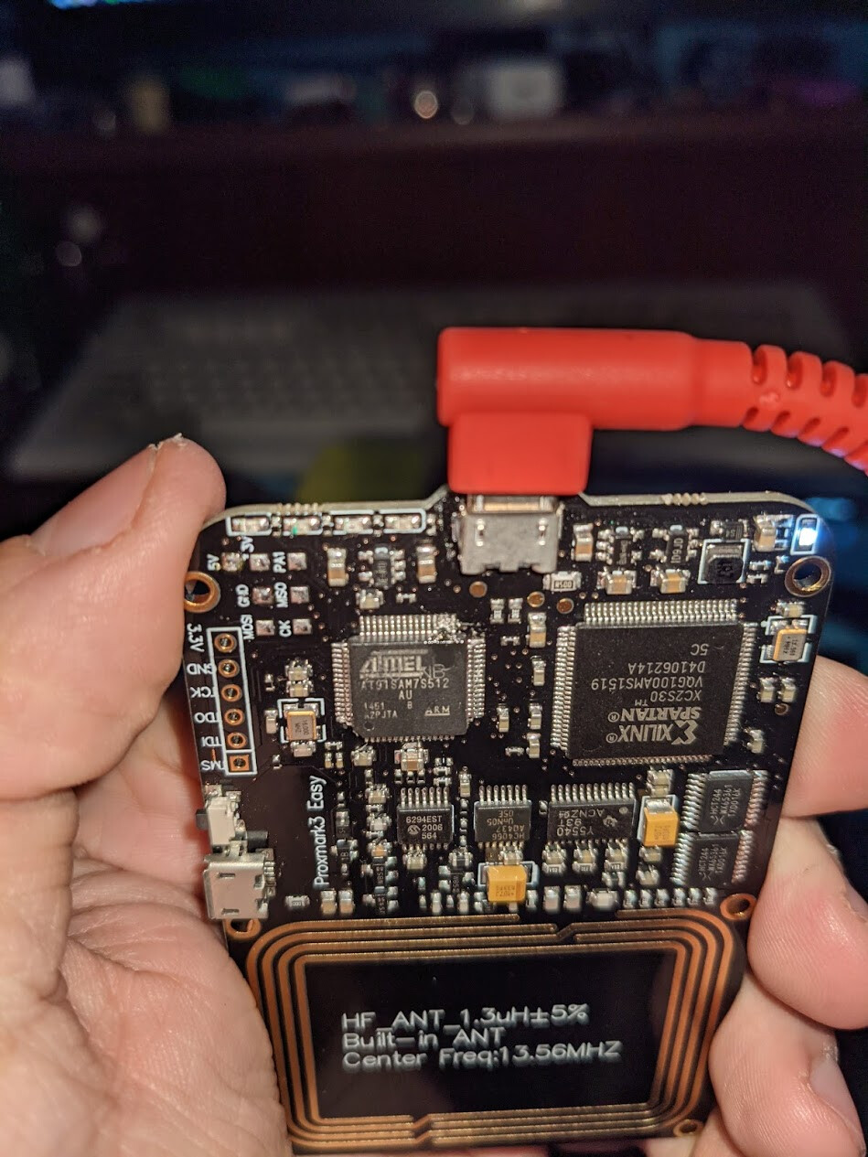
Okay, major, MAJOR breakthrough! I got the physical UART working on the PM3 Easy! This will allow communication via the PinePhone headphone jack, and the PM3 Easy, bypassing USB-CDC.
To the point where @Pilgrimsmaster, would you mind moving this whole convo to a new thread in the projects category (maybe called PinePhone Proxmark case or something?) ?
This is going to be a long post with a lot of explanation.
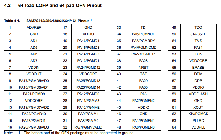
So, I knew the ARM chip used in the PM3 Easy and RDV4 has onboard USART/UART (can act as either), by reading the datasheet listed in the proxmark github repo, along with the uart_nodes.md document in the repo. This datasheet here.
And here’s uart_notes.md. This document is only relevant to the RDV4, and primarily talks about the FPC connector on the RDV4. In the context of the RDV4, the only thing that really uses the exposed USART on the FPC is the bluetooth addon. They mention that it’s possible to connect using an FTDI cable, but the easy is never mentioned.
Regardless, I knew that the MCU is the same in the RDV4 and the easy (at least if you have the 512 version of the easy). I knew that they had to have the same internal USART built-in.
However, one problem was, the MCU used here is highly programmable. Nowhere in the datasheet does it say what pins are being used for USART0 or USART1.
So, I went digging in the source a bit.
I finally found this in at91sam7s512.h:
#define AT91C_PA5_RXD0     (AT91C_PIO_PA5) //  USART 0 Receive Data
#define AT91C_PA5_NPCS3    (AT91C_PIO_PA5) //  SPI Peripheral Chip Select 3
#define AT91C_PIO_PA6        (1 <<  6) // Pin Controlled by PA6
#define AT91C_PA6_TXD0     (AT91C_PIO_PA6) //  USART 0 Transmit Data
along with
#define AT91C_PA21_RXD1     (AT91C_PIO_PA21) //  USART 1 Receive Data
#define AT91C_PA21_PCK1     (AT91C_PIO_PA21) //  PMC Programmable Clock Output 1
#define AT91C_PIO_PA22       (1 << 22) // Pin Controlled by PA22
#define AT91C_PA22_TXD1     (AT91C_PIO_PA22) //  USART 1 Transmit Data
This was fantastic, as now I knew the pins used for both USART0 and USART1. I didn’t know which one they were using for the FPC connection on the RDV4, so I started with USART0.
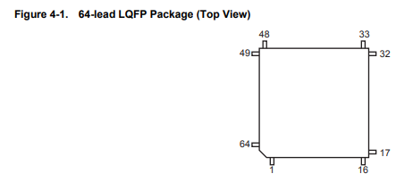
I knew USART 0 was using pins PA5 and PA6, from the defines found earlier. So, those were pins 34, and 35.
Since I knew that the pins wouldn’t really have been used for anything else, I decided to very carefully lift them away from the board, to allow me to solder to them.
It was barely visible to the naked eye, but I managed to get the right pins lifted. I quickly plugged it in to make sure it still worked, and everything was fine.
Soldered it up, including a ground. Hooked it up to a serial port (using an Arduino with the MCU removed), and…
nothing.
After double checking things a few times, making sure I got TX and RX right, I looked through the code again, and saw this in config_gpio.h:
// RDV40 has no HIRAW/LORAW,  its used for FPC
#define GPIO_MUXSEL_HIRAW   AT91C_PIO_PA21
#define GPIO_MUXSEL_LORAW   AT91C_PIO_PA22

Up above, you can see that USART1 uses PA21 and PA22 for its RX and TX respectively. In this block, it mentioned that those pins are used for the FPC on the RDV4, so clearly the RDV4 is using USART1 for the FPC connection. Wish I had seen that earlier, would have stopped me from disconnecting USART0, which appears to potentially be used for communicating with the FPGA for LF operations? The pins snapped off on USART0 when I attempted to reconnect them, which sucks, but learning experience. LF operations don’t work on this PM easy anymore, so I’ll have to pick up another one. Regardless, the rest of this still applies, if I hadn’t have been so gung-ho for trying USART0 before seeing config_gpio.h.
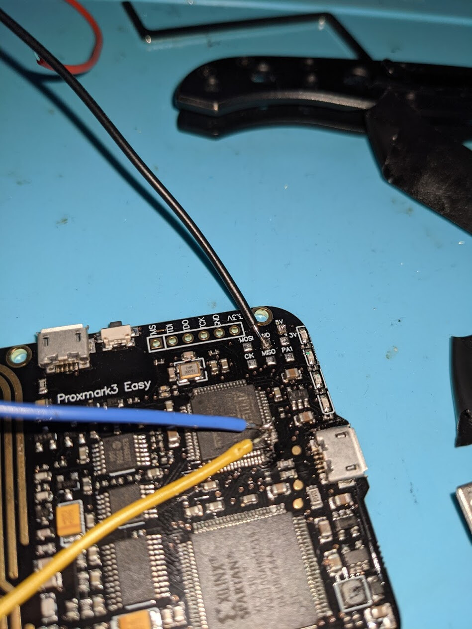
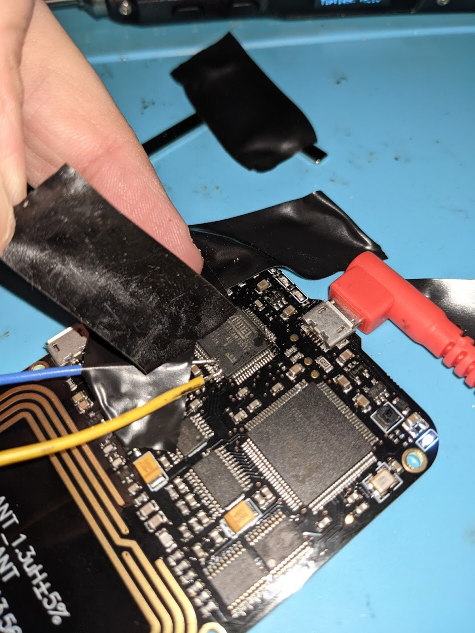
So, I did the same pin-lift and solder procedure as before, on pins 11 and 14 (the tape is to hold the very stiff wire down, to stop it from bending the pins too much).
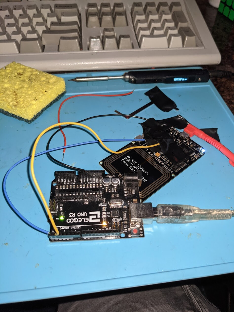
I then connected to the
PM3 normally over USB, then the arduino via the utility picocom, and tried to use the
usart tx d command to send a string over serial. I had tried this when connected to USART0 with no luck. This time, that string appeared in picocom

I was connected to the right USART.
However, once I got this done, another issue came to light. I had to actually put the proxmark into the right mode. In the uart_nodes.md file, it mentions
"connect the host client to the Proxmark3 via this USART instead of USB-CDC, this is the FPC_USART_HOST option you can add to PLATFORM_EXTRAS in Makefile.platform . The most used way is through the BT add-on (blue shark) that we will cover later. Instead of BT add-on, we can also use e.g. a FTDI cable (mostly for internal development, it's much slower than USB-CDC anyway) or in the future other ways to connect the host such as a USART-to-Wi-Fi bridge."
However, when I attempted to recompile, I got the error that FPC_USART_HOST was not recognized as an option. However, since they mentioned that the BT add-on was the most common use for it, I realized that they had updated it to instead use the option BTADDON under Makefile.platform.
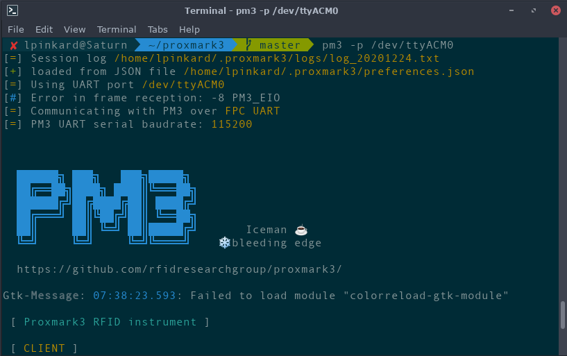
So, I recompiled, flashed the PM3, plugged it into power (via a wall charger), and attempted to connect. It connected right up  It connected in fpc mode, as if it was an RDV4 connecting over bluetooth.
I had some occasional bad frames (it mentions it in the screenshot above), but this was from me actively fiddling with the connection. Once I sat back and let it be, it was connecting fine, in FPC_UART mode, as if my
PM3 Easy was suddenly an RDV4
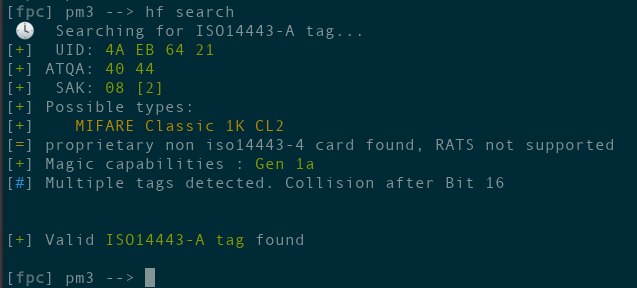
Still works too
(this isn’t a card I use for anything, by the way).
I feel now that it’s 100% possible to package this into a rather slim case for the pinephone, Would just have to solder a headphone breakout cable to the exposed USART1 pins, and 3D print a TPU case to throw it in.
Hopefully this was a decent write-up, if anyone has any questions, feel free to ask.
Especially with the spacer removed, it’s 100% possible to get this thing down to a pretty slim form-factor, all things considered.