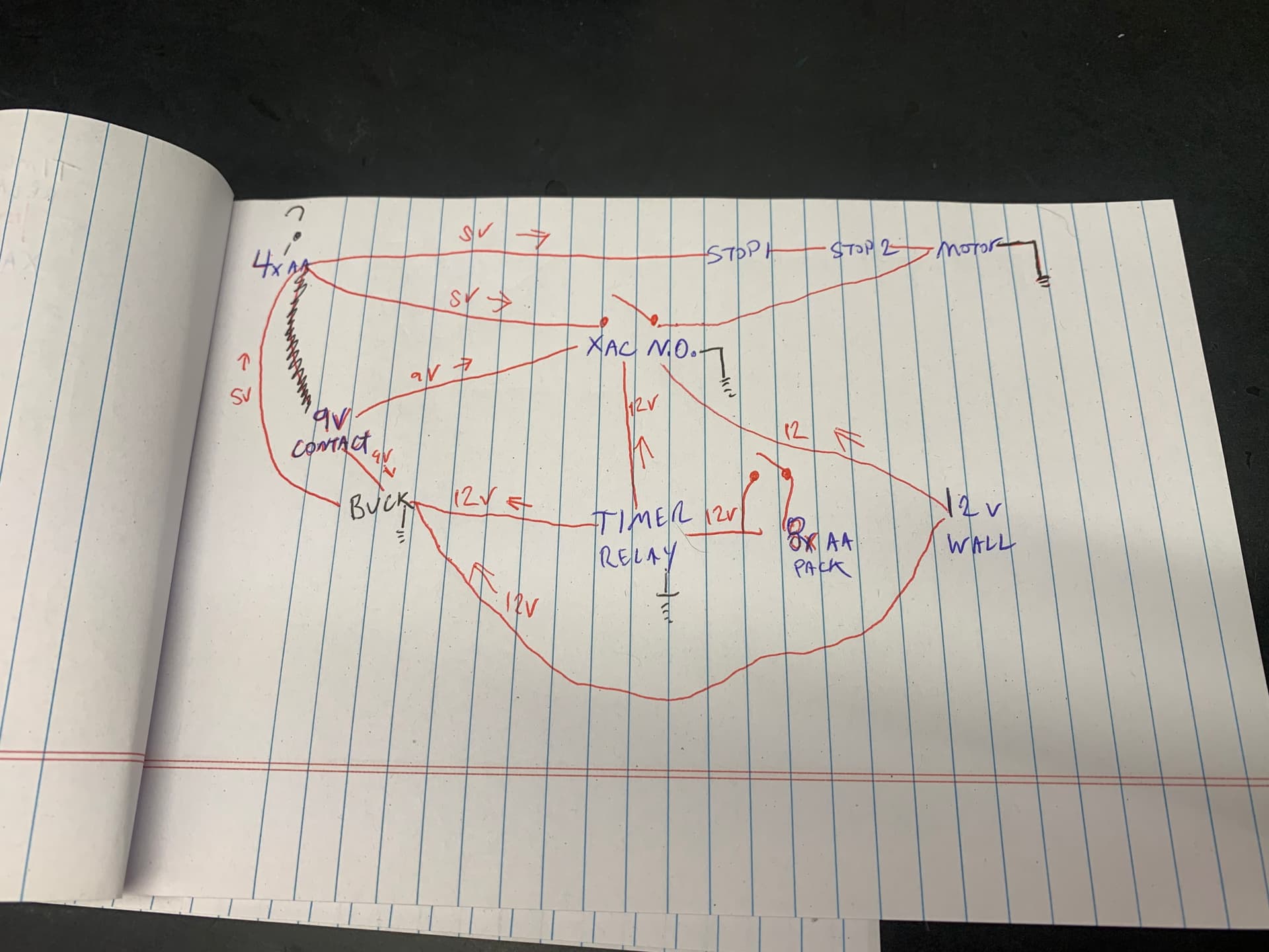
Here is what I think would work, IF you are willing to replace the entire control circuitry. Replace the two stop switches with normally closed ones connected in series.
+ Power - switch 1 - switch 2 - motor - - Power
If the bar is not holding one of the switches open then it will just run until the other switch opens.
Now you just need some way to trigger it to start it moving. If you connect the XAC up to momentarily power the motor it will move the motor away from the current stop switch and the above mechanism should kick in.
The XAC should basically trigger a relay that connects between + Power and the motor.
The only piece that you need to worry about in this case is that the XAC will always be drawing power.
Does this make sense to you?
If you wanted to get fancy you could add a third normally open switch that is closed by the door being closed in series with the other two (or better yet, in series with the motor so the XAC can’t trigger the motor if the door is open).
Because of the use of the cam the motor is always turning in the same direction, using NC switches as the stop switches would mean that as long as the bar is not at one extreme or the other the motor is powered. If the motor is powered it is headed towards a position where it will open one of the stop switches and will stop. The only issue then is moving the bar far enough to close the stop switch. That is all we are using the XAC for.
I think I get what your suggesting, and I’m super appreciative for it… gives me a spark of hope
I don’t mind removing the original control panel, was kinda nice to have as a backup but I do like appeal of rfid only
It’s a lower hanging fruit than me learning how to make a microcontroller… idk what it is… thanks to
my adhd I usually pick up most things pretty quickly and easily… that stuff just doesn’t click for me…
I think the xACv2 in 1 second mode, should be enough to get release a stop switch
As far as powering the xACv2, I’m not opposed to running a wire, safe already has mounting holes
I’ll likely also use the same 12vdc ups that’s in the big safe
The question is,
Do I want to have a timer circuit of some
Kind?… that would let it have a battery that could last for months at a time…. But would need some kind of button press to activate it
Or constant wired power; with pure contactless wave of the hand rfid
I suppose I could rig a switch to flip between battery and plugged in modes
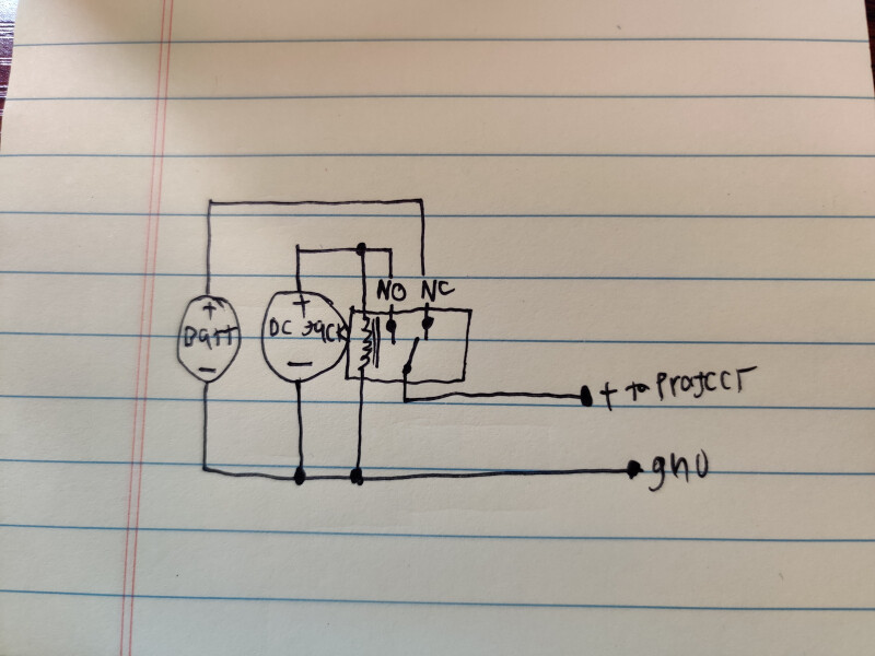
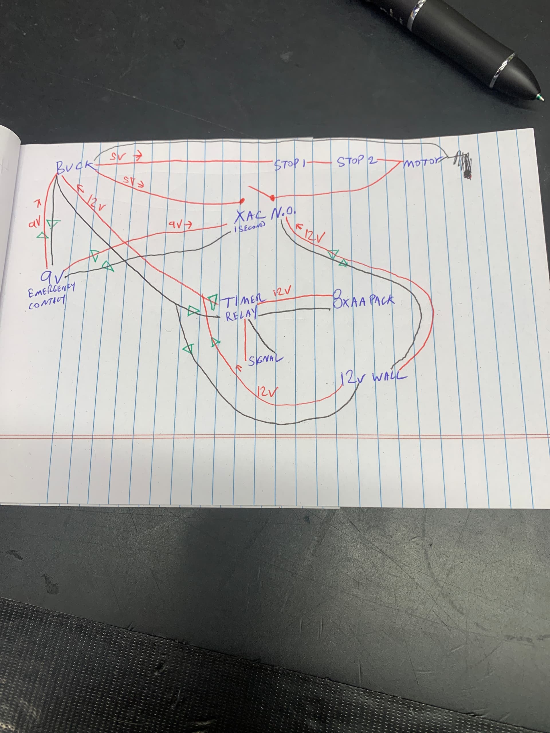
Could totally do both. I believe some dc barrel jacks come with a switch contact to signal something has been plugged in. another way I can see it being done is with a SPDT relay shown in the schematic.
with the battery being connected to the relays NC it will draw no power while on battery but automatically switch over when it gets power from the DC jack. You could probably have it so the relay will automatically bypass whatever power protection circuit you decide to use if you were to put in a DPDT relay instead. I like relays, they’re neat.
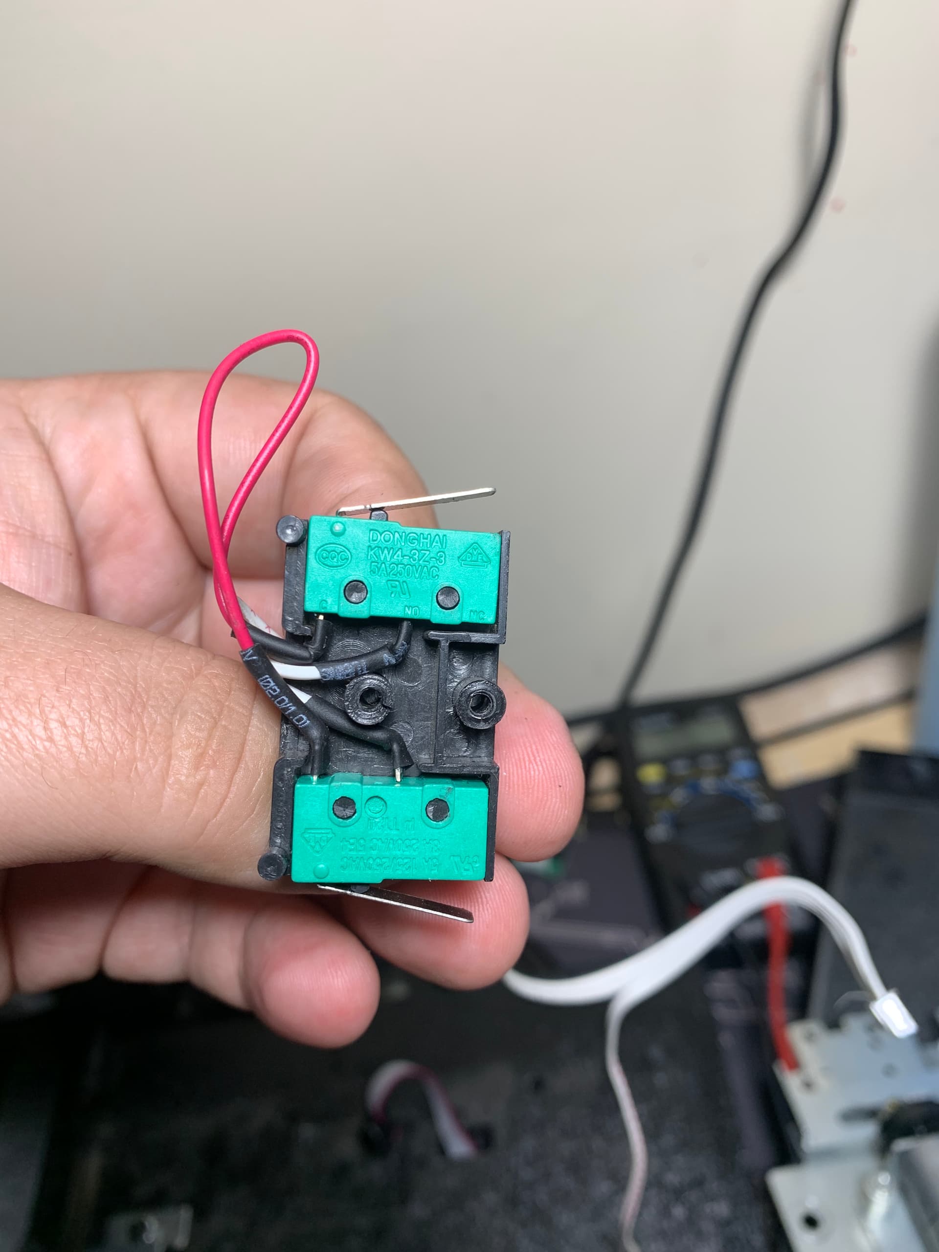
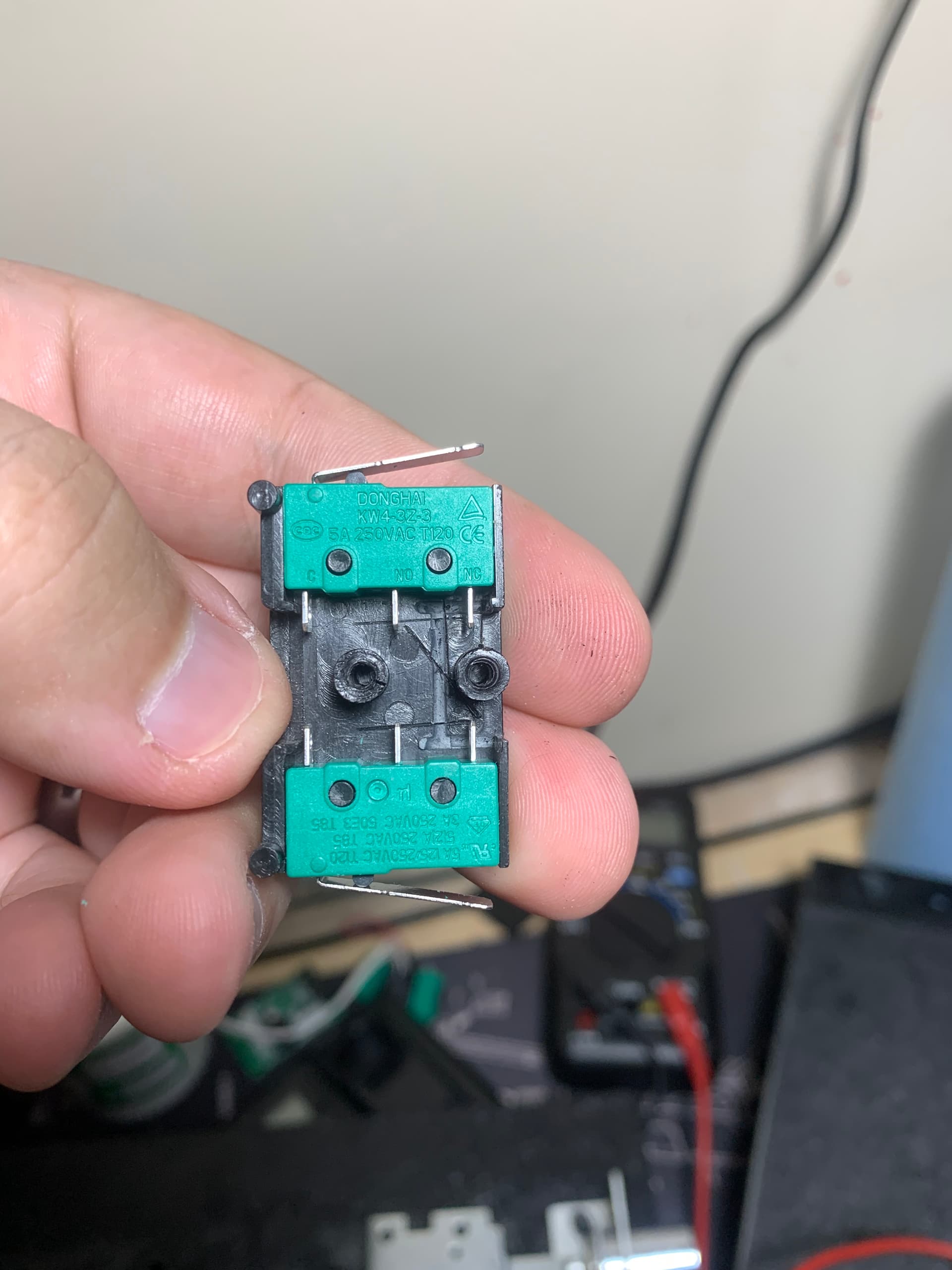
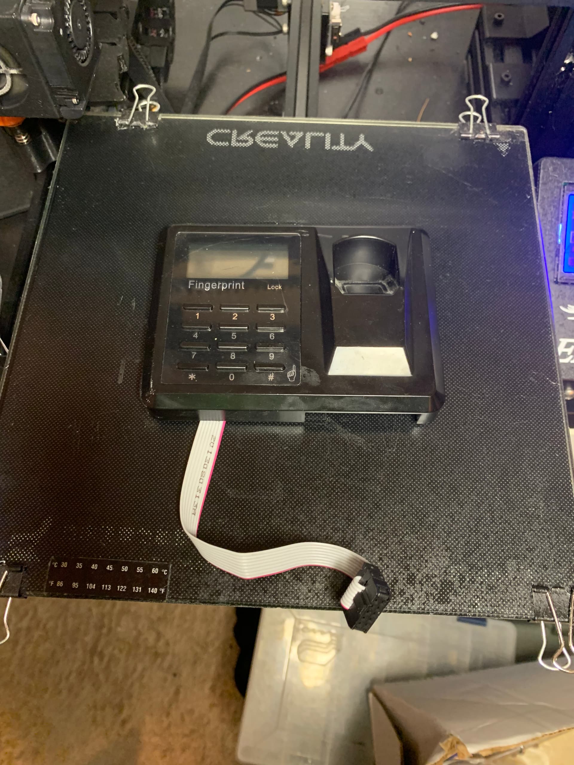
I’m googling to try and figure out what size these microswitches are… and I see in the google image search that there are 3 pins… and I start thinking why that might be
Flip back to my picture and there’s a giant NC position staring at me lol
Good news I don’t need new switches
edit
they either cut the contact or this model didn’t have a NC option whatever new switches ordered lol
Just making sure, given these are just going to be in series… there’s no reason I couldn’t / shouldn’t just connect the 2 NC pins from the switches? Might be cleaner, and hoping to try and make the wiring a bit cleaner as there is limited space inside the motor compartment
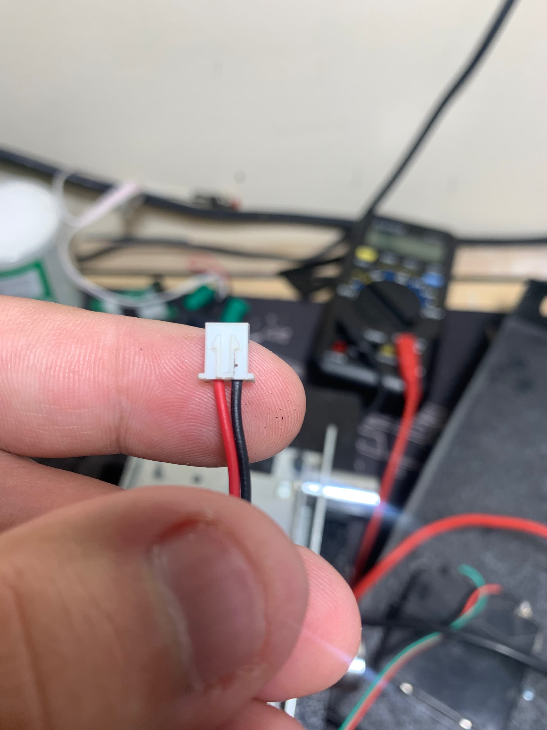
Next step, is I don’t think I want to make a permanent mod if I don’t have to, because I wouldn’t mind moving to their larger version of this safe… appears to use the same setup… so would let me swap everything easy
so I need to track down this connector type, I thought I had a bag of these… but what I have is a hair too small
So I came across this thing in trying to learn if capacitive button/switches have a parasitic draw
very intrigued,
Could use this to activate a relay that powers the xac
that toggle mode is also pretty cool
Lots of power options to consider
In case it wasn’t clear, I’m planning to 3D print a new front plate and stick the xac antenna behind it like the big safe… but knowing that switch doesn’t need direct contact and can work thru plastic could lead to some hidden switch trickery…
I also wonder if it could activate thru auto glass, say a side window… that could open up some possibilities
Ok well, as I worried I don’t have enough space inside the original mechanism cover, space is limited and shoving a couple boards and a ton of wire in is going to get tricky
So a 8xAA batterry will sit below the mechanism cover on the inside of the door, a bit less clean but I guess easier access when I need to change batteries
Going to use one of those 12v timer relays to limit power to the reader when it isn’t plugged in
I don’t think I’ll need a second relay, if I wire 12v power cord, and the output of the timer relay in parallel
The part I’m sure I’m going to catch flak for, is I think I’ll keep the original 4xaa’s to power the motor itself
Having 2 battery packs is less than ideal, but
it’s already there and takes up space either way
It’s easier than figuring out how to step down voltage without causing a constant drain
Place the voltage regulators after the switches. A buck converter will give you the best efficiency in this case and those are available as fully assembled modules. Or if you want something cheap and simple, mesure the current draw of the motor and see if you can get away with a power resistor in series with the motor.
I got all worried on my drive in today, that I hadn’t taken I to account the size of the front panel in regards to my print bed… I was super worried I wouldn’t be able to fit it
Breadboard, relays, Battery pack, and dc plug are all on the way
Hopefully I’ll be able to function test everything on the breadboard before I fully build everything
But I’ve never really messed with a breadboard… can you just jam regular wire ends in? I usually only see DuPont jumpers used…
I think I might do the 9v contacts also
I’m already running a bunch of parallel circuits, what’s one more… and I have the 9v battery holders
I think I might have a couple left over small
Buck converters… maybe I will use them… just wastes the original 4x aa battery holder that takes up space either way
Don’t get Zeners, those allow current to flow backwards once the specified reverse voltage is reached! And you only need one per power supply.
I was thinking of something like a 1N4001 or similar. Get some normal silicon diodes that can handle the current draw of the motor, that’s all you need.
Here’s the datasheet for the one I mentioned above, any of the part numbers it mentions will do the job: (as long as the motor requires less than one amp)
I really wish I had a decent way to draw an schematic on my phone right now. I’m sorry I can’t explain it better right now.


")