Thanks to @DonFire 's excellent guide I got my Proxmark back up and running.
Since then I’ve been playing around with all of the things I can do with it. One of my main concerns with the board was the lack of a proper case. Knowing me, I was bound to short something and make the device more brick-like than my botched firmware update did.
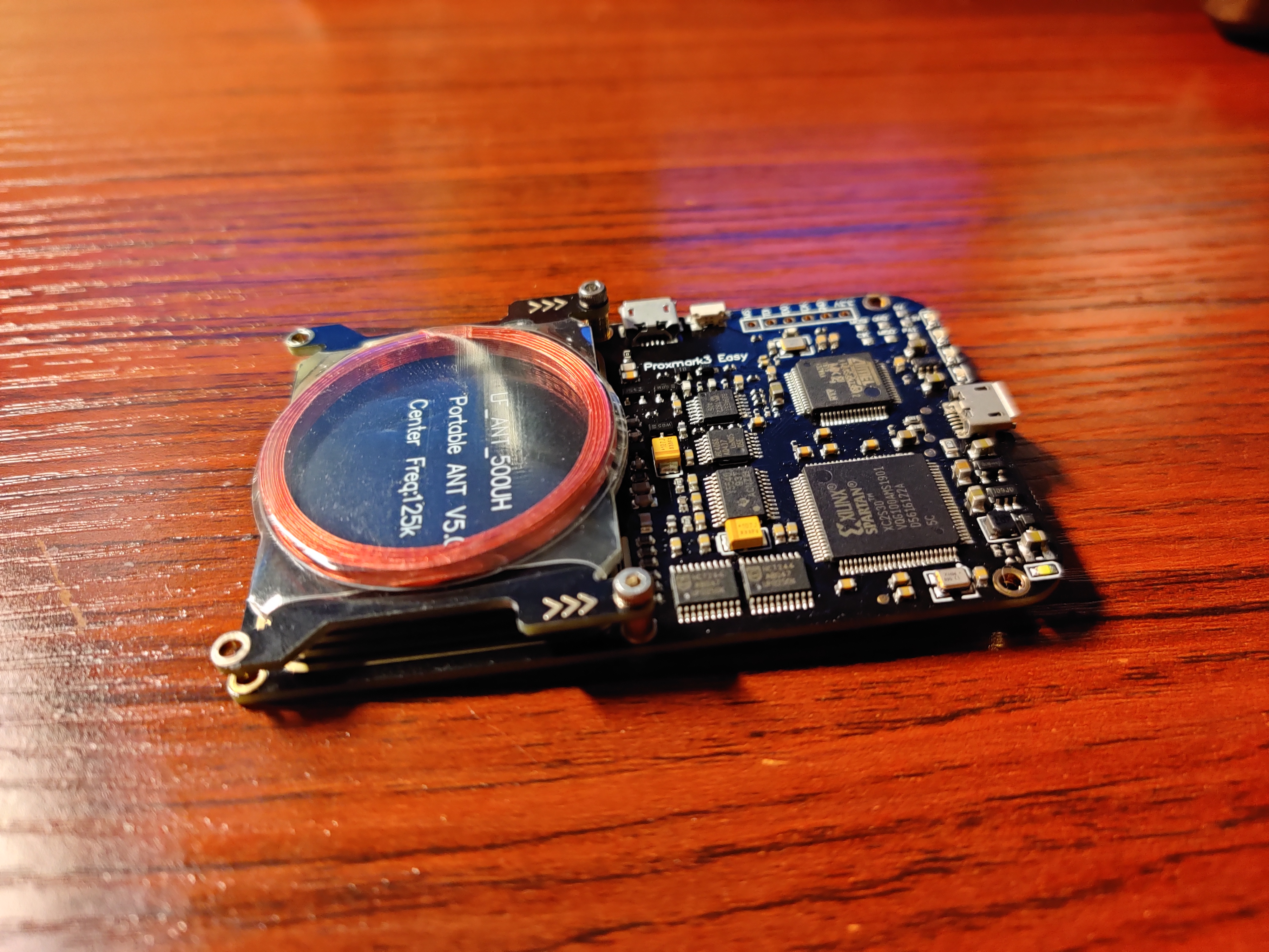
So I started designing a case for it and while I was thinking about the design I had a realization. The middle PCB is barely useful. It raises the LF antenna away from the main PCB and covers the traces of the HF antenna. This got me messing around with a variety of orientations and attachment methods for the LF antenna. What I found was the higher the antenna was from the main PCB the higher the Q factor would go with the opposite happening if the antenna was placed so only one set of standoffs separated them. This led me to finding a more minimal case design and a practical mod. Rotate the LF antenna so it is over the HF antenna and remove the middle PCB all together. This reduces the Proxmarks height from 15.8mm down to 11.5mm. The only downside is having to flip the Proxmark over or placing it on top of HF tags to be read which I find an acceptable compromise.
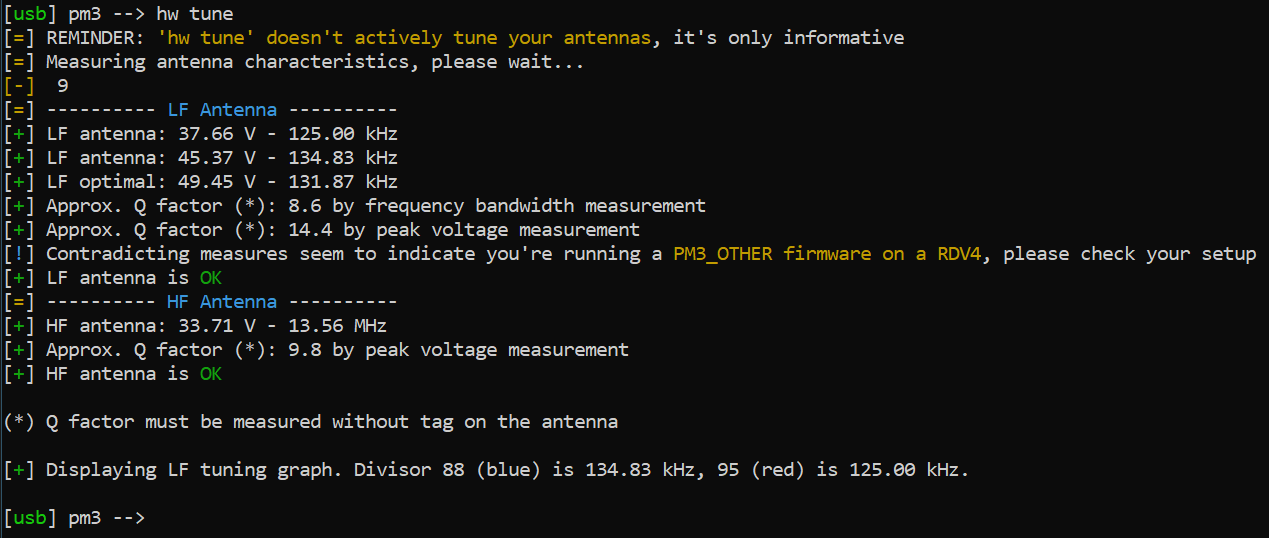
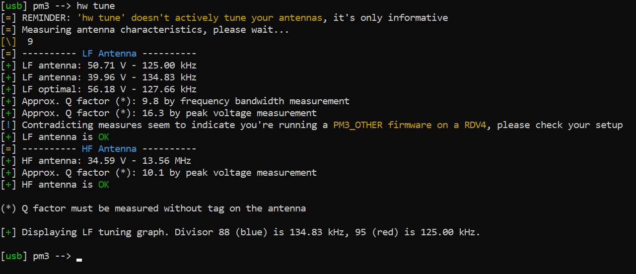
I also found the new orientation lead to better performance when reading or writing the LF side of my NEXT. The hw tune command shows the Q factor increased by approximately 12%
Important notes:
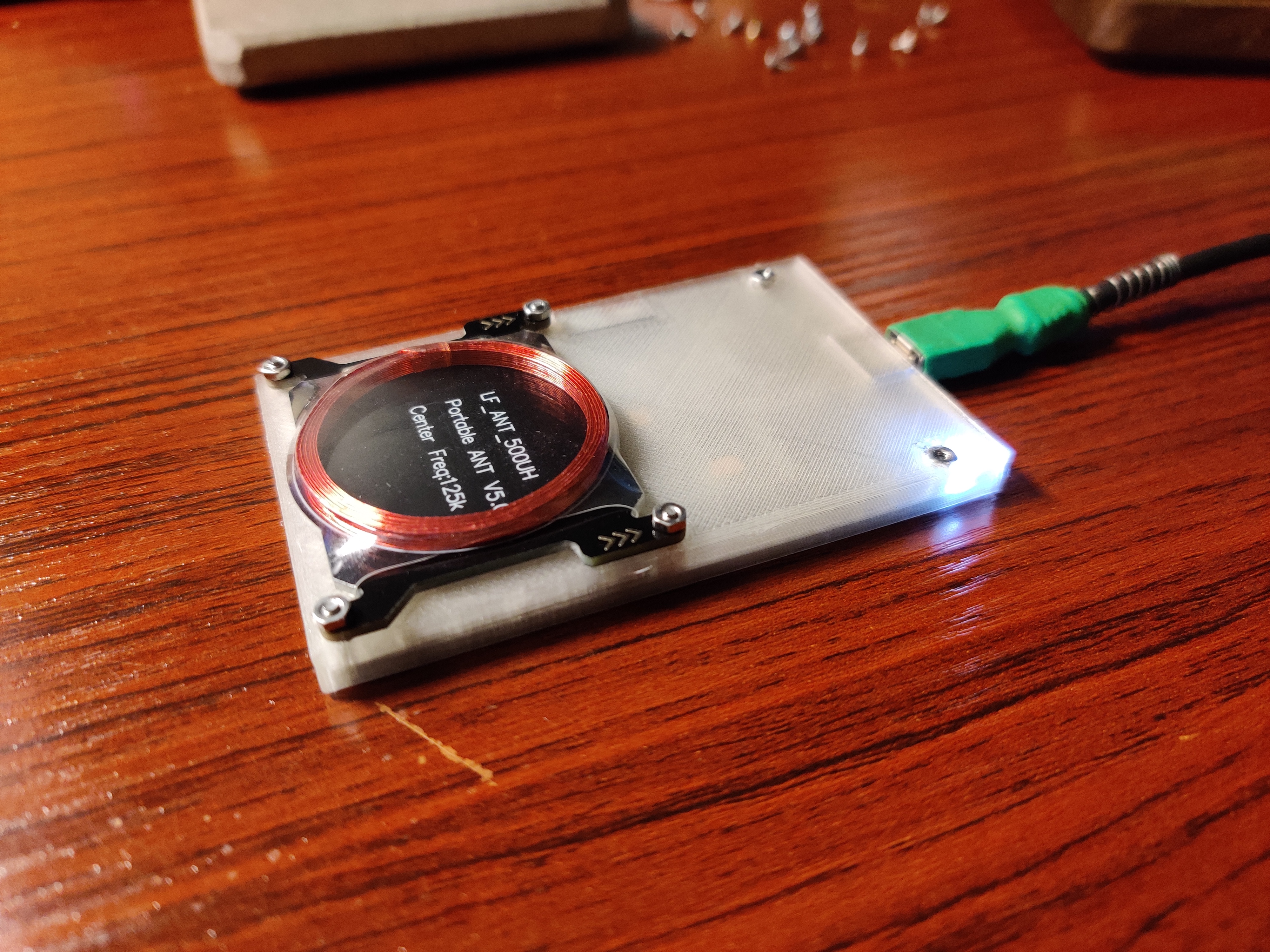
The middle holes are bigger to accept a pair of the original standoffs. Those standoffs are required as they are part of the circuit for the LF antenna. Also note the arrows on the antenna board should always be over the middle holes on the Proxmark. For the rest of the attachments I used Phillips head countersunk M2x10 screws from the bottom to the top 4 holes of the antenna. The last two holes are Phillips head countersunk M2x6 with M2 hex nuts melted into the plastic.
proxmark3easycase.zip (226.8 KB)