6 Likes
That’s pretty fuckin tight.
I just received a board I designed for another project with onboard capacitors snuck on. I’ll be able to do some testing this week and then I can order a jumbo flex test board with a ton of permutations of the stickers and CoM conversions
2 Likes
I would live to donate, but I dont have any money. I would live to help.
Okay so I finally got enough funds and bandwidth to order another revision of the CoM conversion board. I snuck a couple onboard capacitor tests in the negative space of other flex arrays I was ordering over the past few months and collected some data. I also contacted PCBWay and got more information about their flex PCB stackup thicknesses.
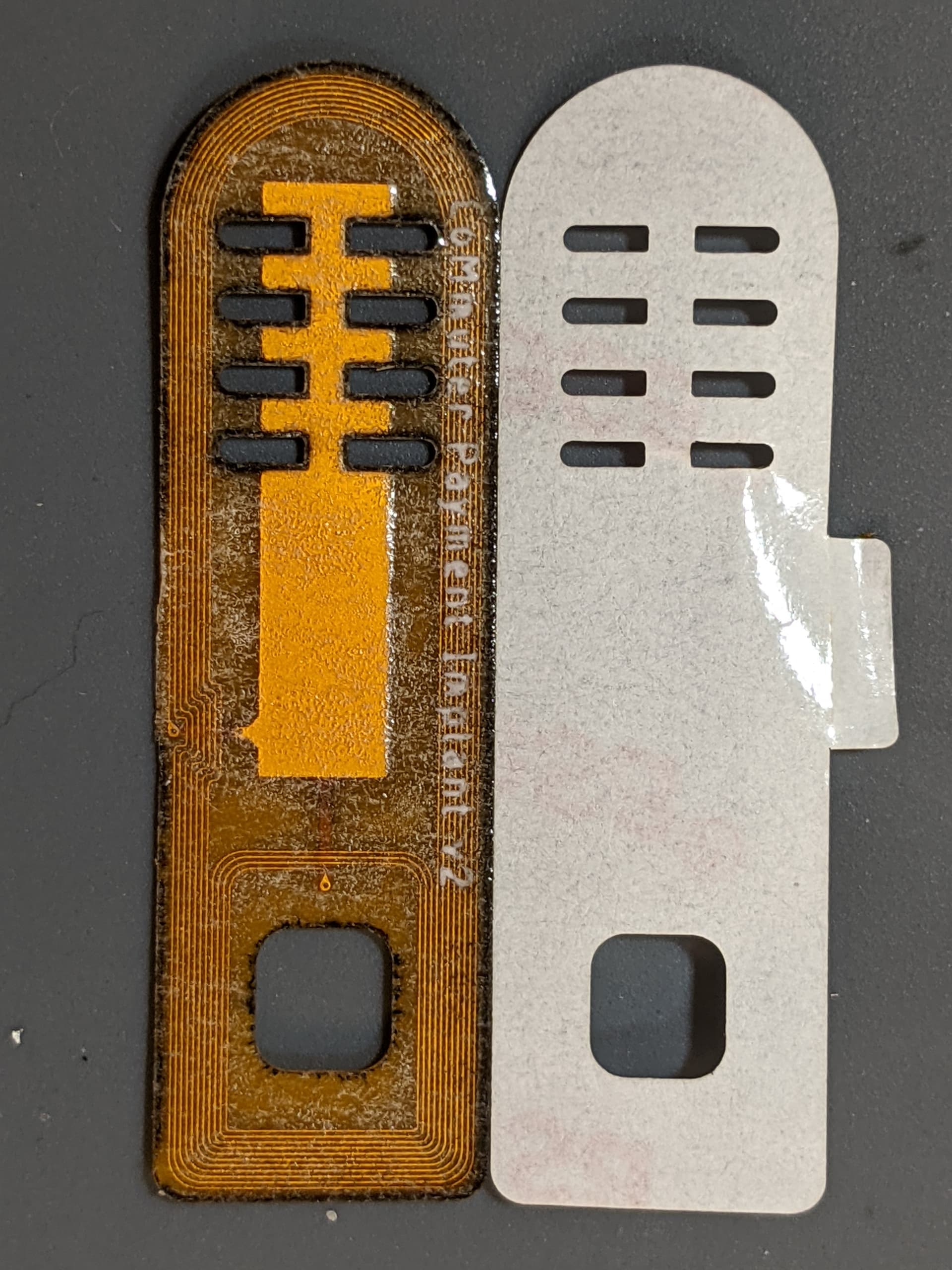
Standard flex in 0.26mm thickness with 2oz/ft^2 copper and 2U ENIG plating thickness
- Polyimide Substrate: 0.025mm (my calcs indicate 0.0298mm)
- Copper Layer: 0.07mm
- Coverlay Thickness
- Yellow: 0.063mm
- Black: 0.05mm
- White: 0.068mm
Here’s the relevant calculation again for anyone who wants to use it in the future
C = ε0 * εr * (A/d)
- ε0 (vacuum permittivity) = 8.8541878128⋅10−12 F/m
- εr (relative permittivity polyimide) = 3.4
- A (area of plates) = 0.0001m2 (1cm2)
- d (distance between plates) = 0.0000298m
Example: 1cm2 on 0.26mm FPC
C = (8.8541878128*10^(−12)) * (3.4) * (0.0001m2 / 0.0000298m)
C = 101.0pF
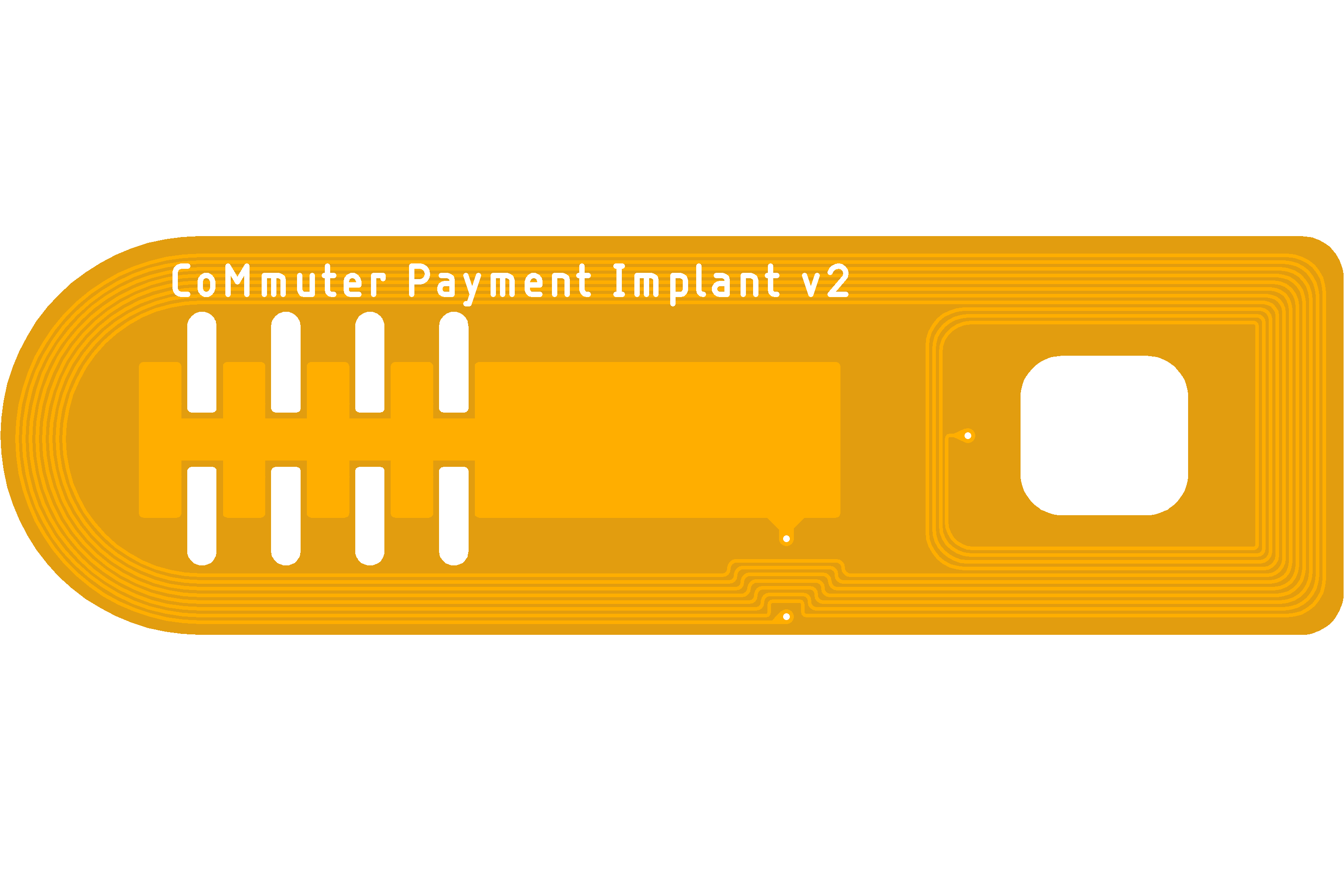
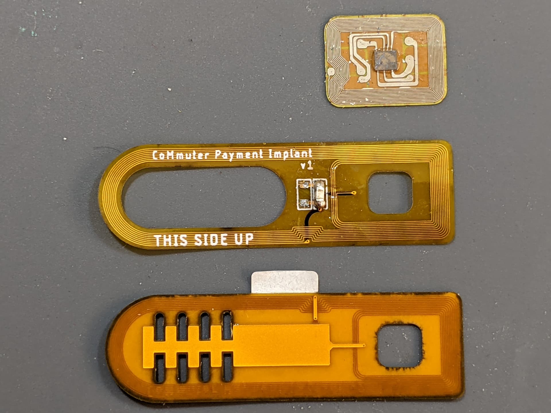
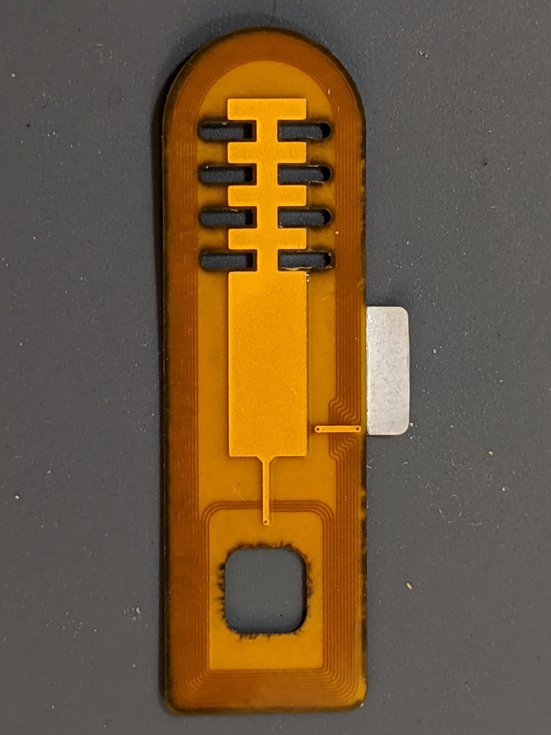
So with all that done and the testing I did on the v1 CoM conversion I was able to make this new one. I wasn’t 100% confident that the calculations would match reality closely enough for my purposes, so I added some extra capacitive plates that can be cut before encapsulation to modify the tuning. This could also help address a broader range of modules, because @non-bin shared some data about an Australian CoM module that had a different resonant peak.
8 Likes
Looks great,
As usual I can only understand about 70% of your knowledge bombs… ![]() …but it sounds great
…but it sounds great
It looks like this is still shooting for flex needle format?
How do you think this will fair with the shitty veriphone readers?
What little I understand, it looks to be similar footprint, and I would expect some added inefficiency when it couples to the chip also
Unless there’s some new voodoo I’m missing
1 Like
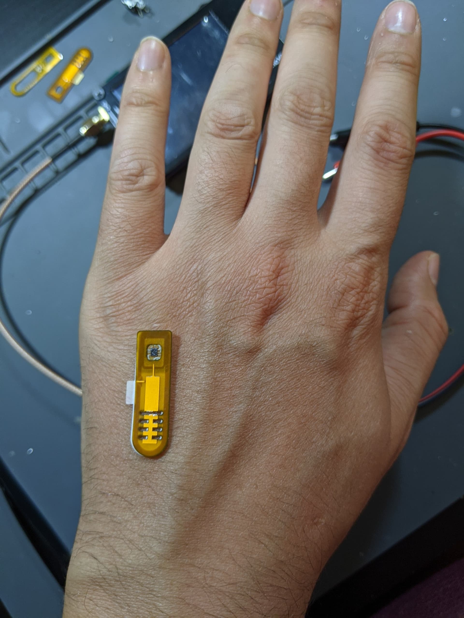
Unfortunately because of the width of CoM modules, this implant will never be compatible with the flex needle. It’s 9mm x 32mm currently, and after encapsulation will be more like 11. It couples much better than standard flex implants though because of the size, even with verifone readers as seen in a video I posted earlier in the thread.
2 Likes
Unfortunately the board needs another adjustment. The capacitance was much higher than I calculated. I’ll make another pass.
7 Likes
I just ordered the third and likely final revision. After it arrives I’ll send the whole assembly to Amal for encapsulation.
3 Likes
Question,
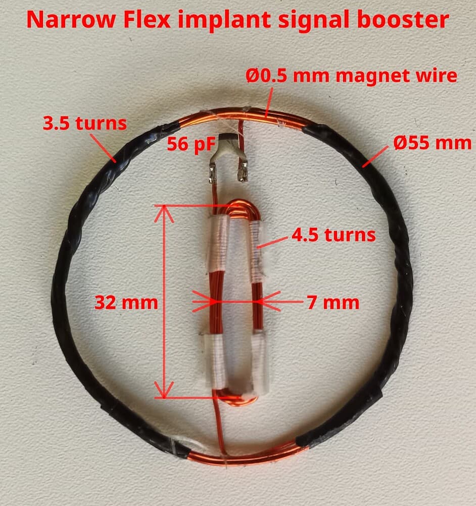
I see that you are using that round antenna
Would it be advantageous to rip a antenna out of a terminal, and use that for testing? since that’s what we are trying to couple with
It would be interesting, but I don’t think very informative. All it’s going to show is that the coupling between readers and implants is bad because they’re not card sized, which we already knew. The coupling factor k is only affected by the size of the coils and their position relative to each other. Physics isn’t on our side. Because of the size we’ll likely get better coupling than we ever could with a standard flex though.
2 Likes

8 Likes
Very informative video, the visualisation through the VNA really helps.
Would it be possible to show the coupling between a Apex Mega and the verifone reader?
2 Likes
@Satur9 Could this theoretically be placed on the back of a cellphone, or would that interfere with its internals somehow?
This could definitely be placed on the back of a cell phone to improve the coupling between the large NFC antenna and the small ones in implants (flex or glass). This one is discussing shaped for the CoM module, but I was planning to design another with a design more targeted at x-series using the insights I gained from this one.
2 Likes
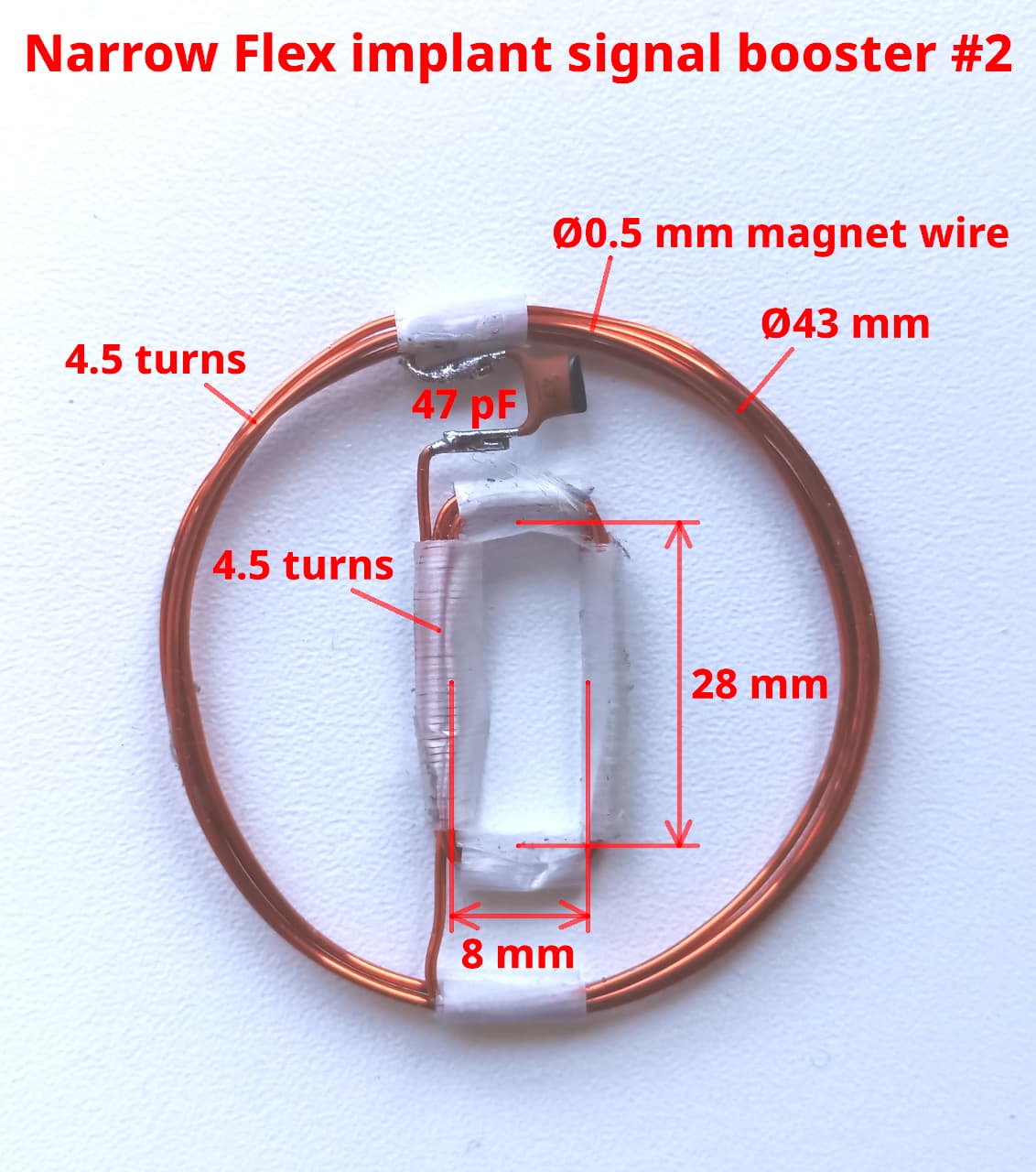
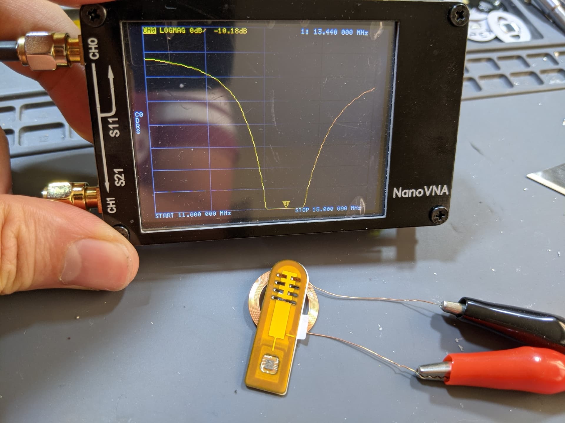
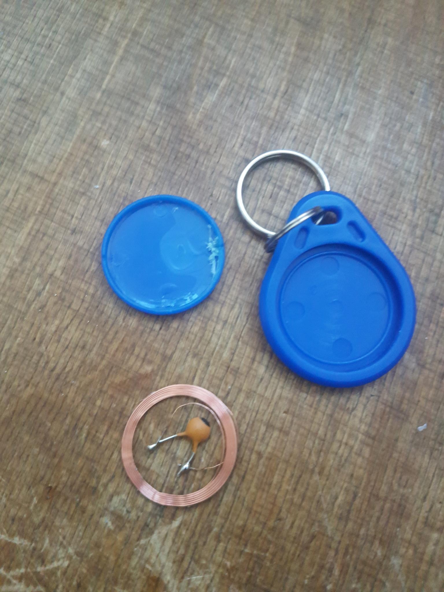
I made a simple repeater by repurposing the antenna of a comemrcial NFC NDEF keyfob. Cut away the MOB chip and replaced it with a 22pF capacitor. I measured the resonant frequency using a NanoVNA, and I got close enough (peak at 13.9 MHz). Taped it to the back of my phone (the case hides it), and it improves the read performance of my Flex quite a bit.
9 Likes
I mean….If you maybe want to maybe make another….lol
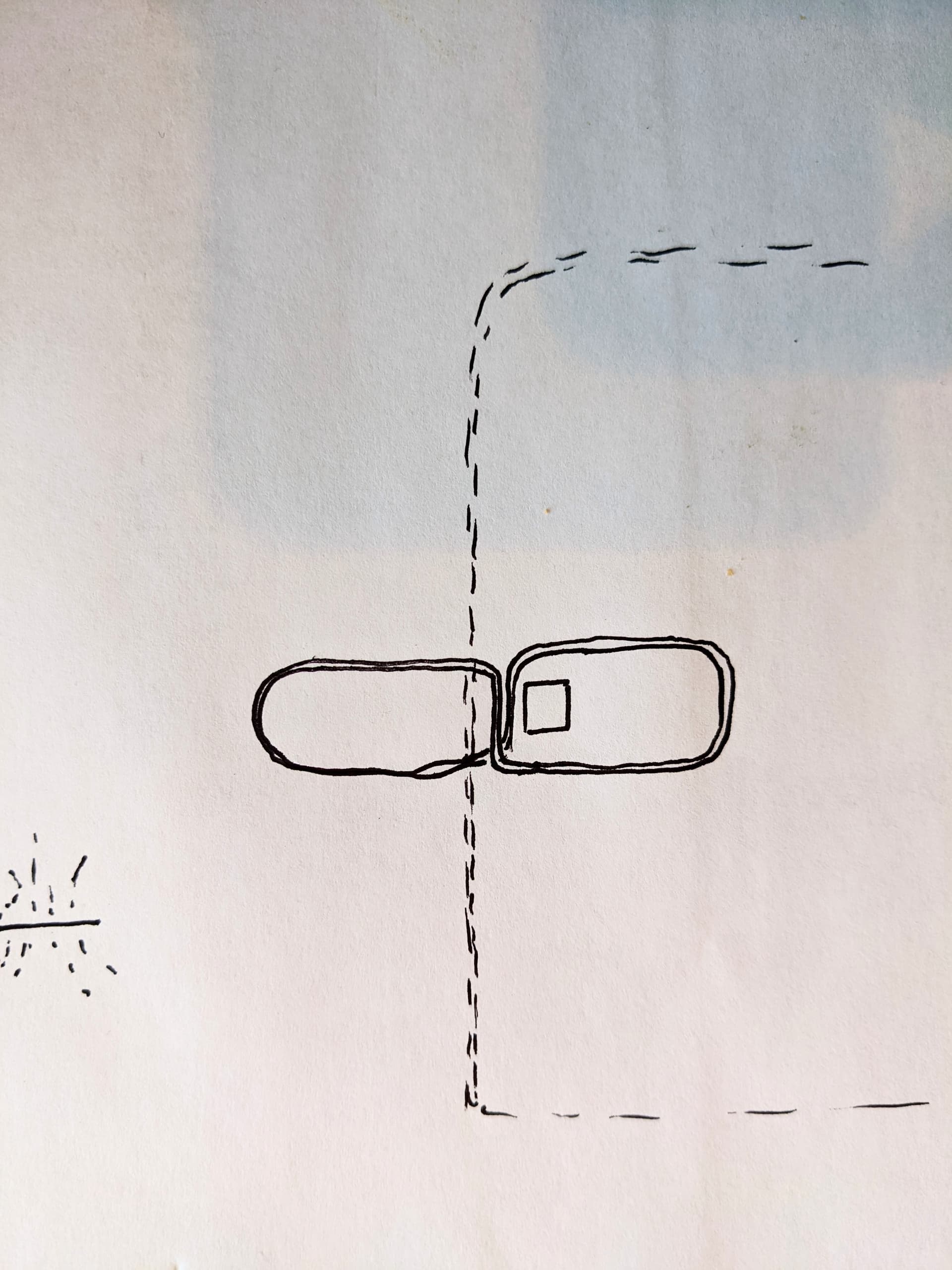
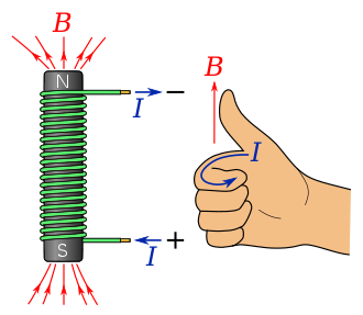
Sorry I didn’t mean to ignore this, I just forgot to respond. I’m pretty sure a single coil formed into a figure 8 with a direction change in the middle would cancel itself out because of the right hand rule.
Was there some specific advantage you thought it would add?
The dashed lines are the section of a larger coil, like a large coil design for a larger badge reader.