This thread is almost the virtual DT bar, where everybody knows your (user)name.
I’m sure someone with awesome photoshop skills can replace Ted Danson’s head with Amal’s ![]()
This thread is almost the virtual DT bar, where everybody knows your (user)name.
I’m sure someone with awesome photoshop skills can replace Ted Danson’s head with Amal’s ![]()
God… that’s a little too accurate
Take your like sir
Norm!
Now we’re going to need a photorealistic avatar of Amal for Chillout VR or something.
:robot_gundam:
Yeeeep, what a very frustrating name change smh. Why they felt the need to change it is beyond me.
Time for your favorite program,
Stupid electrical questions from Erie
Got in the capacitors to replaced the blown out one…
I was under the impression capacitors were non polarized… so I was planning to just desolder and slam a new one in wham bam
Then I looked at the new ones and one leg is longer… uh oh… that means things
A few google searches later, looks like capacitors do have a direction… weird…. But the one I’m replacing is… no longer attached…
What the best / easiest method to determine direction for install?
Is there a symbol on the board?
Can you see a trace to follow?
Can you post a photo of the board?
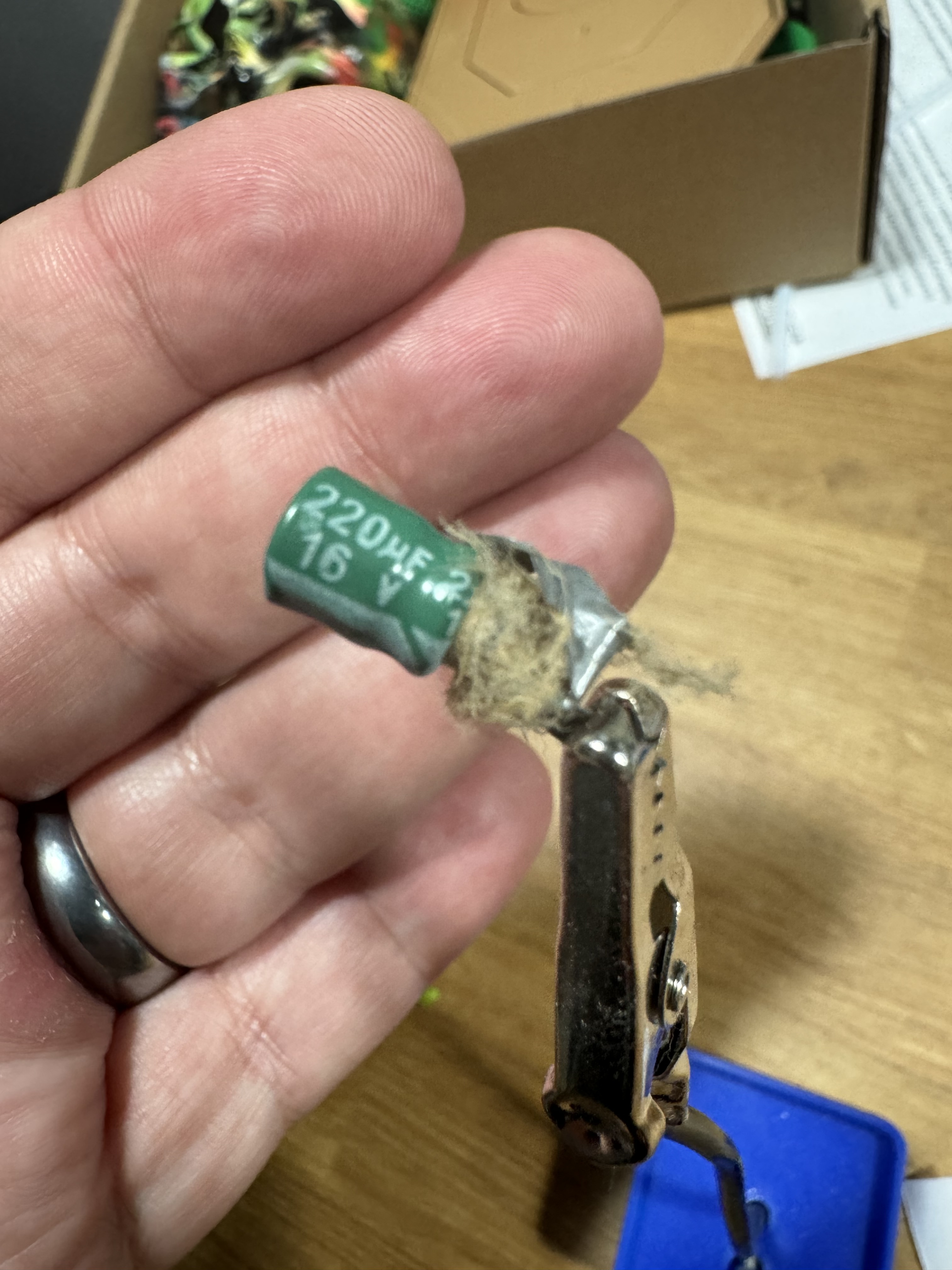
And a photo of the Cap?
This will likely be your Cathode (negative) check on the casing for symbols to confirm.
IF it lives between those diodes, check to see where the trace goes from diode to cathode at the ground end (circled in red)
@enginerd Thoughts???
Also
I hope you’ve done a Brazilian and cleaned all that pussy fur off
lol, I’m planning to when I get to the actual work…
Best part is, this is after I already lighty brushed like 90% of it off…
That is correct, the negative is marked with a band on the side of the cap.
There might be a marking under what’s left of the original capacitor as the forum AI said.
Pictures of both sides of the board with the base of the old cap removed could be helpful. Along with a diagram or explanation of were the pins on the connectors go.
I’d personally start by checking the output voltage of the power supply for the unit, both DC and AC, the AC component should be relatively close to 0. I kinda want to rule out the PSU as the cause of the explosion.
One easy way to determine the polarity might be to connect the board without the capacitor and checking the voltage across the pads for it with a multimeter.
Gotcha
The power adapter that was plugging into this was the correct voltage, but the incorrect amperage… only 1amp instead of the 2.5 requested… and then I left it plugged in… longer … than I meant to
I bought a correct version once I realized, hoping that was the source of it not powering up
That wasn’t the cause of the dead capacitor but replacing the power adapter is definitely a good idea.