So, I got permission from my boss today to inspect some of the active readers in the building. He enjoyed learning about my personal upgrades!
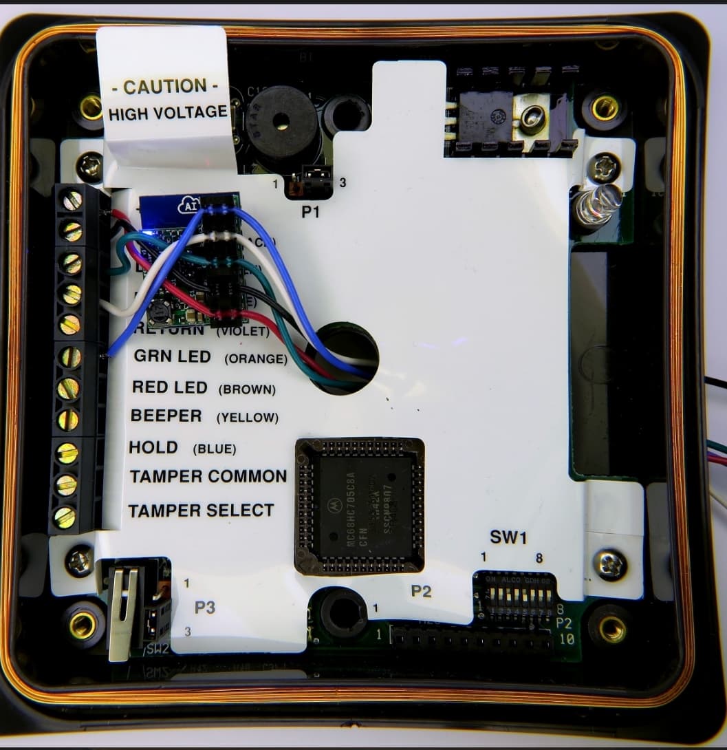
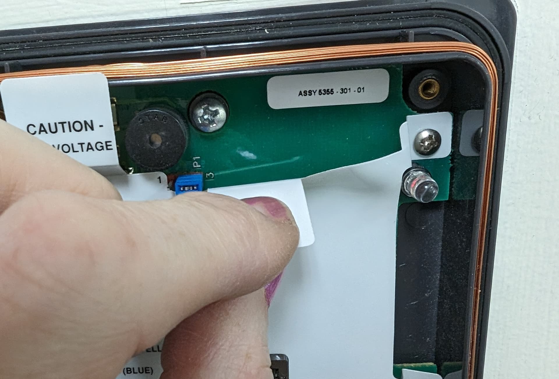
I took apart the CardKey reader that I can use with my implant, and another one in the same room that doesn’t see me. All the jumpers and dipswitches were the same, but I noticed two things.
The reader that doesn’t see me with the case on can read my implant with the cover off.
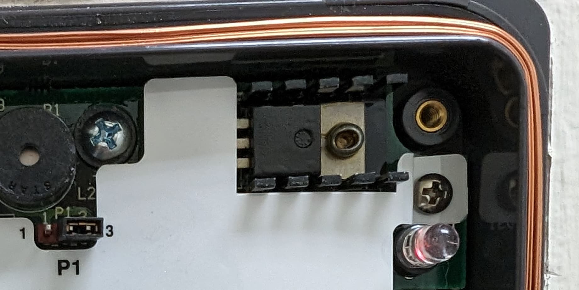
There is an extra chipset on the readers that don’t see my implant.
On the left is a reader that only sees me with the cover off. There is an extra chipset in the upper right of the board.
On the right is the reader that sees me regardless of whether the cover is on or off.
Maybe you are right and that these are just very low power output readers. I’m kinda disappointed that there wasn’t a setting that I could change and make everything better.
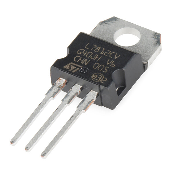
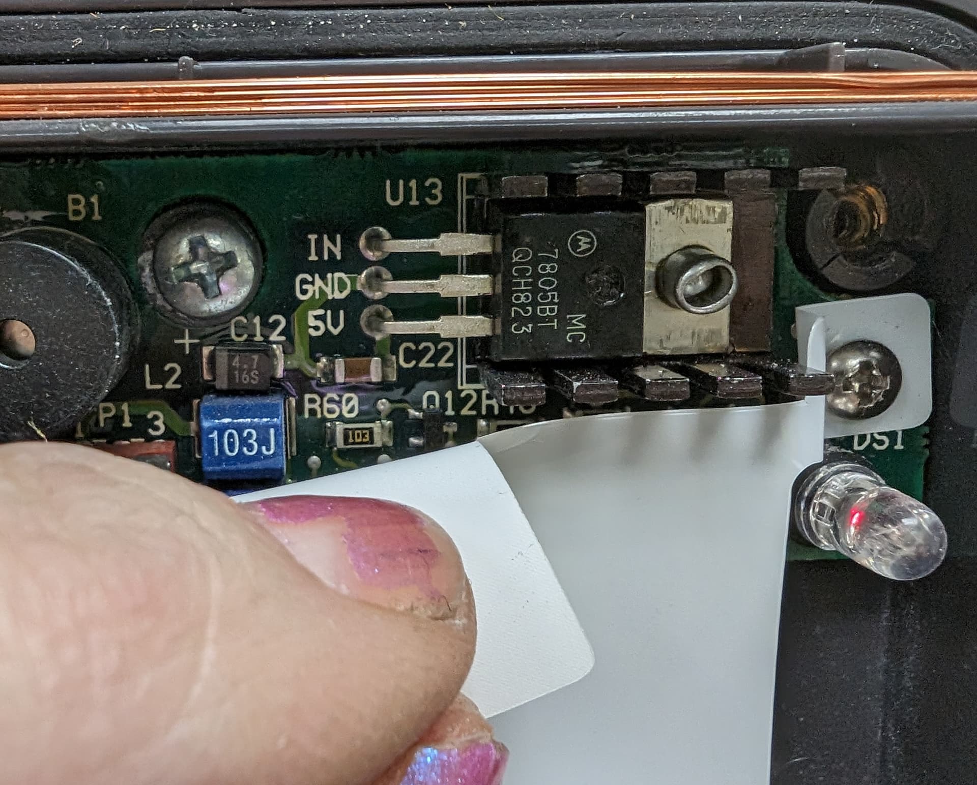
that chip is definitely a voltage regulator… it has heat fins on it and everything. I wonder if that voltage regulator is dropping the operational voltage of the unit to the point where it’s weak sauce.
you could check field strength with the RDC or XFD and testing in a specific consistent spot on the reader but checking the range or distance from the reader the LED begins to light.
If you have a voltmeter you could also test the DC+ and GROUND input lines on both readers to see what voltage is coming in, just to confirm.
finally, i wonder if there is a terminal block on the version missing the voltage regulator that the regulator actually plugs into? can you see behind that little white section overhanging the area where the regulator might sit? is there a terminal block in there or some sort if DIP receiver block for the regulator? Even if there isn’t, my bet is there is a jumper wire in there that puts the full supply voltage into the actual circuit. Either a jumper exists in a DIP or terminal receiver, or the jumper is soldered into the main PCB… but that’s probably the issue. A lot of supply voltages are like 24V or higher because the long runs of wire required to power these things drop DC voltage quite badly, so typically a high voltage is sent down the wire but it’s too high for the reader and thus a voltage regulator is put in place… but if one of these regulated readers is put on a line that has only nominal voltage, it will probably operate at far less than operational levels. For example, if you put a 12V DC regulator in place but supply 12V into the input, it will output like 10v or worse.
If the input voltages are the same for both readers on the DC+ and GROUND and are within operational limits for the reader, and there is a jumper wire in the working reader… I might push a little to see if you can remove the regulator in one of the readers and see how it performs Risky I know, but that’s what I would do.
I am unsure what that chip is in the corner because I don’t have documentation that explains it.
It’s possible it could be a step down or power limiter. I know some readers can be as low as 5v and as much as 20v. It’s likely just 5v readers that are restricting the coupling to your chip if it reads with the cover off…
Yes. I can do both of these things when I am back at this facility on Wednesday or Thursday.
That’s exciting! I will look!
Considering I have a reader WITH the regulator chip that currently doesn’t control any active doors at my disposal, I see the risk as minimal.
Mua ha ha.
As the reader would not normally be switching high power loads, a regulator is the more likely possibility over a mosfet. Also it’s close proximity to the hi/lo power jumper in would lead me to believe it’s related to the reader power supply.
I searched through the Fcc filings and there’s no mention of this device officially from HID. but i think the consenses is that it is the reason for the poor read.
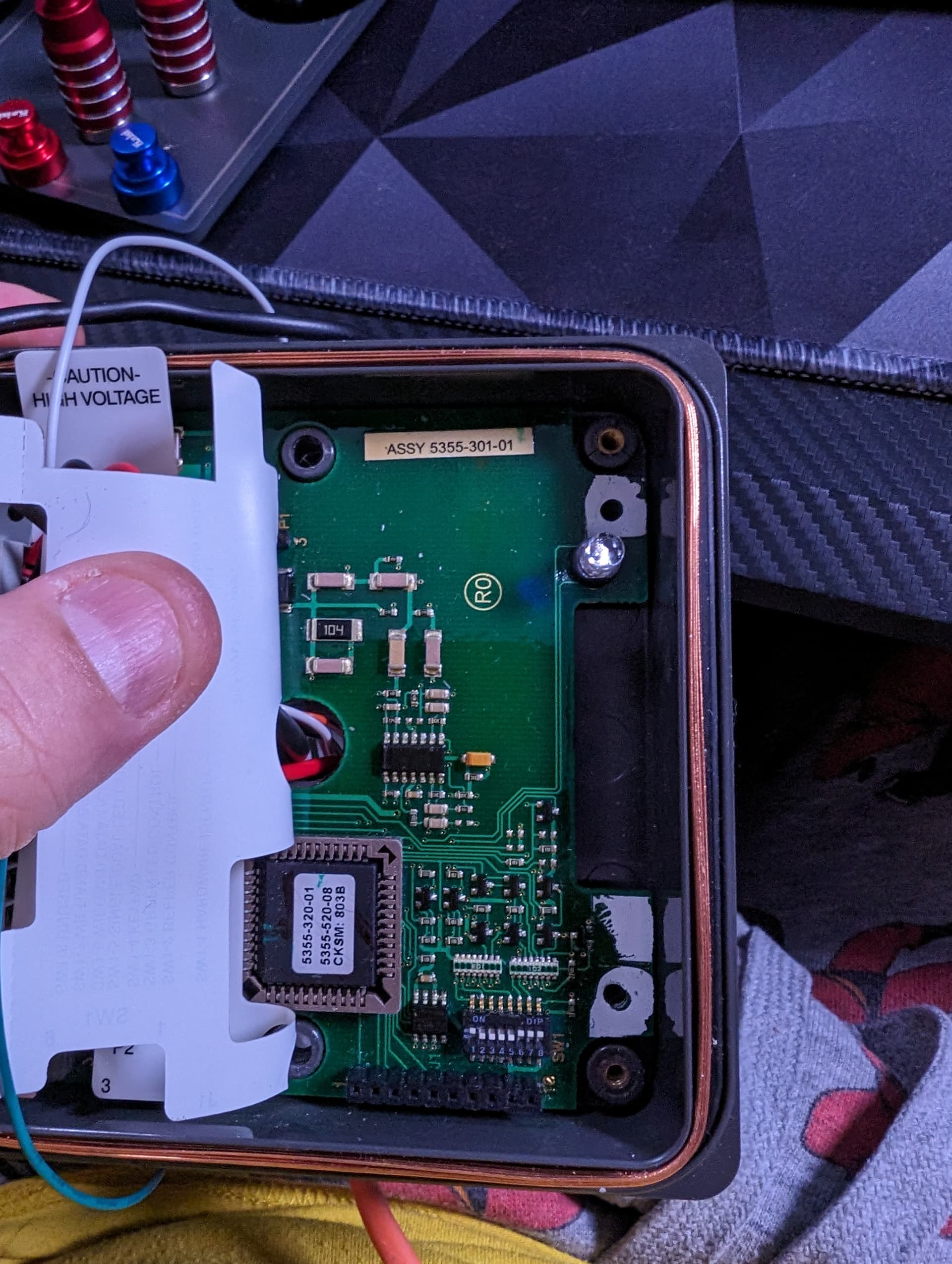
OK. So here are the new data from today.
I am working with three readers that are all labeled CardKey, but I am wondering now if one of them is actually an HID with a CardKey cover on it.
Back Warehouse always sees my NExT.
OPTIC Room only sees my NExT with the cover off.
Room 107 (unused) sees my NExT with the cover off if I get JUST the right position, and it’s not easy.
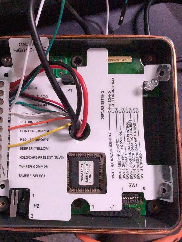
Back Warehouse does not have the voltage regulator chip / MOSFET, nor does it even have a place for one. It has a read range of about 5mm with XFD and 3 in with RDC. The input voltage on a multimeter is 13.48v.
OPTIC Room has a voltage regulator chip / MOSFET that has labels on it (photo below). It appears welded to the board. It has a read range of about 15mm with XFD and 4 in with RDC. The input voltage on a multimeter is 13.08v. I was surprised by the read-range on this one since this one only sees my NExT with the cover off.
Room 107 (unused) has a voltage regulator chip / MOSFET that has no labels on it (photo provided previously). It appears welded to the board. It has a read range of about 1mm with XFD and 1.5 in with RDC. The input voltage on a multimeter is 13.40v.
@amal wins that’s a voltage regulator. When you are testing with the multimeter what points are you using to get your reading?
So if you look at the picture that regulator is stepping down. The 13v youre seeing at the post, to 5v to the board. This to me explains the lower range.
I’m reading at DC+ and GROUND, so well before it hits the regulator.
Since this appears to be a permanent fixture of these boards, I probably don’t have much hope of making successful modifications, do I?
theres a super sketch thing you could do. i wasnt going to mention it because it has potential to fry the reader, but you could always attempt to jumper the regulator pin IN and 5v. note that it will fry components not rated for 5+v almost instantly.
I am guessing these clones of the HID readers can only operate at 5v and thats why it is there. so thats why it is stepping the voltage down from 13.
I am unaware of any software that can bypass it but im also pretty new to all this.
OMG! There is an HID ProxPro on an unused Clean Room door. What if I swapped that HID out for the CardKey that’s on the Main Warehouse door that I use every day and I put the CardKey on the unused Clean Room door instead?!?
I also have some ideas here. On the reader with the regulator that puts out power but gets bad reads with the NExT (OPTIC Room), try holding your hand further away. This is one of those classic dirty power reader scenarios where the output power is plenty strong enough, but the circuit and the reader is probably not sensitive enough to hear the faint cries of the small NExT over the noise it’s producing.
Sometimes you can improve signal by moving your transponder out to the edge of the magnetic flux bubble. The downside is that it’s kind of hard to hit that in free space every time versus holding your hand right up to the reader. But it’s worth a shot.
I’m also curious what the output voltages of these regulators are. I would test to make sure they are actually putting out five volts or one might be out of spec and causing poor performance.
I actually just asked my boss about moving the HID, and he said that there is a server that records what badges enter which doors, so I don’t think it would be a simple swap out. I would end up locking everyone who doesn’t have Clean Room access out of the Warehouse! LOL.
I’ll try this and see what happens!
Where would I measure that from? The 5v pin on the voltage regulator?
these readers have an internal identifier that is used in software management that identifies them and they can label them so i dont think that would work.
really? is that ID sent with each card scan? i thought these types of readers wired to a controller used the wire ports for ID, making the readers interchangeable.