Hi everyone,
I started working on this quick little project for some fun at home and as there has been recent interest in hobbyist electronics I thought I would turn it into a lightweight tutorial / documentation of the process I went through for the project. This is an overlap of my hobbies and my job so please feel free to point out stuff that I have not explained clearly as I would love this to be useful for people with zero background in this sort of thing! ![]()
It also may be particularly useful for renters who can not modify their house significantly but want to add smart lock capabilities. But the overall goal of this post is more to inspire others to tinker and have fun ![]() .
.
As I only started this project today (2020/04/15), I have not done everything so some parts of this are empty. The change log covers all updates I make ![]() .
.
Project Overview
So the actual project I am working on is connecting a RFID reader to my existing smart home system. I have purchased a commercial RFID reader that has a Weigand interface (most of them do) but I want a simple way of connecting the reader to my door lock. I already have a lot of smart home tech including a wirelessly controlled lock that already communicates with my smart home system. Therefore all I need to do is add a link between my smart home system and the Weigand interface on the reader.
Introduction to Weigand
The Wiegand interface is a de facto standard for access control systems. It is used for RFID readers that you see next to doors across all essentially frequencies (HF, LF and UHF) as well as magnetic swipe cards readers and keypads.
This is great as it makes systems like this project compatible with many protocols.
If I want to add or swap out a reader I do not need to change anything.
For example I may want a keypad for my mum to use when she visits and a reader for my implant, or maybe I want to implement multi factor authentication (MFA). By using Wiegand I have lots of expandability options.
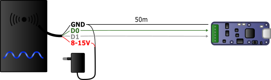
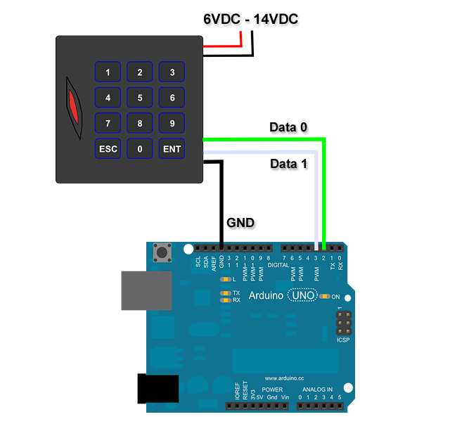
The Wiegand interface is also quite simple wiring wise. It consists of 3 wires one of which is a common ground and two of which are data transmission wires usually called DATA0 and DATA1. These wires usually operate at 5v which is great for most microcontrollers, although some do operate at 3.3v (more on this later).
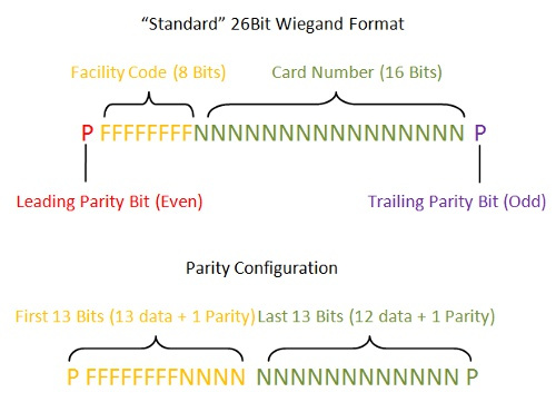
Weigand has multiple common bit lengths 4 bit, 8 bit, 26 bit, 32 bit and 34 bit, for some systems this matters, since we are doing this DIY we can use any reader although a 4 bit ID is easier to brute force than a 34bit ID if that is a concern for you ![]() .
.
If you are following along for your own project keep in mind it would be easy to swap the Wiegand interface for something like this reader sold by DT or any other system you can imagine. I am using Wiegand but make it your own if you want to!
Reader Options
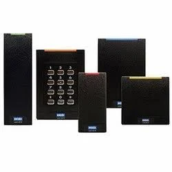
So as I alluded to in the above section the options for Wiegand readers is massive and you are not limited to Wiegand. But since I will be working with Wiegand I will only cover the main categories of Wiegand compatible readers.
For implants ![]() (I assume that is what you are interested in) you will want a LF or HF RFID reader, depending on your needs you may also want a RFID + keypad combination unit.
(I assume that is what you are interested in) you will want a LF or HF RFID reader, depending on your needs you may also want a RFID + keypad combination unit.
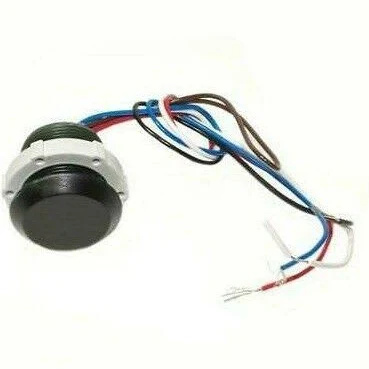
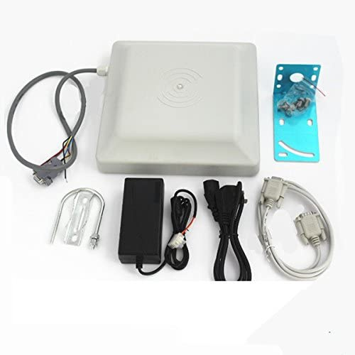
For my project I am actually using a UHF reader for long range reads. I want to be able to have my door unlock without having to do anything other than walk towards my door. At this point in time the only implant that is UHF is a proprietary micro tag designed for lab rats but maybe @amal can work something out for me if this project goes well ![]() , the only thing I worry about is how long lasting UHF tags are since they are usually used for inventory tracking and are considered disposable in many cases.
, the only thing I worry about is how long lasting UHF tags are since they are usually used for inventory tracking and are considered disposable in many cases.
This is the exact reader I am using, I got it from here.
Introduction to Arduino
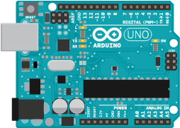
Arduino is an open-source electronic prototyping platform. There are 3 distinct parts to the Arduino ecosystem.
The boards, Arduino compatible boards consist of a microcontroller and a breakout board usually in a specific form factor that allows the addition of shields (add on boards that provide additional functionality without you having to do the wiring) like this RFID shield designed for standard form factor Arduino boards sold by DT.
The Arduino core, a C++ library that is specific to each microcontroller that provides a common wrapper that simplifies the coding process for each microcontroller.
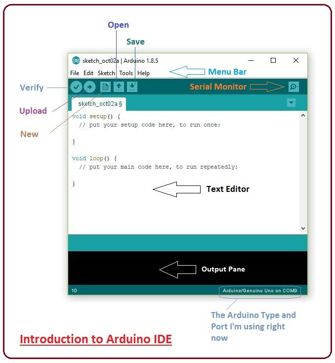
The Arduino IDE, a software application that you develop your code projects (known as sketches) in. It has a heap of useful features that help you while developing and testing your project.
Arduino Options
There are many flavors and form factors of Arduino compatible boards and you can even use a microcontroller directly on a custom circuit board if you wish (I may do that with this project once I finish prototyping but knowing what I am like it may stay on a breadboard forever)
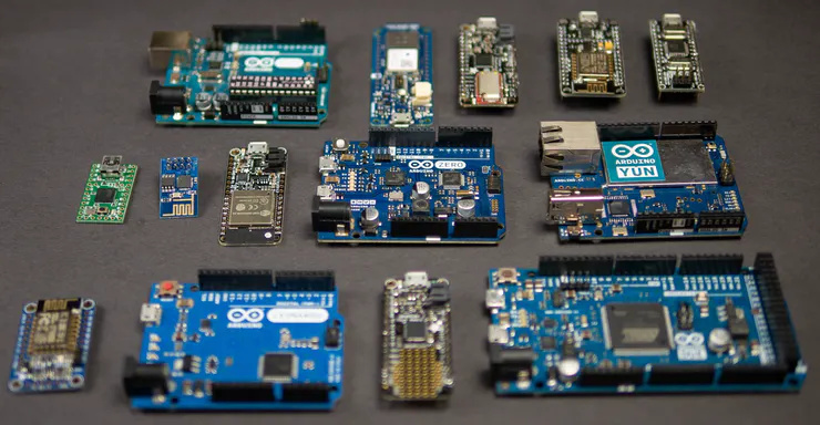
There are too many form factors and microcontroller variants for me to cover. Since there are different pros and cons to each option I will go over why I chose the esp8266.
I do not intend on using any shields so my form factor options are quite open.
I also only intend to connect a single reader and potentially a button, so I need a board with at least 3 IO pins (2 for the DATA0 and DATA1 wires from the reader and 1 for detecting if a button is pressed, this means I can pick a relatively small form factor.
Since I want this to be able to talk to my smart home system I need a way to communicate to the computer running the smart home system. Since I have a zwave and zigbee mesh network in my house I could set this up to communicate over those, I also could use the built in USB to emulate a keyboard (similar to how the [KBR1](https://dangerousthings.com/product/kbr1/ works) or send serial data to a PC. Having said that I prefer WiFi as it lets me remotely communicate with many devices with relative ease. For this I could get a separate WiFi module but there are multiple Arduino that have WiFi built in.
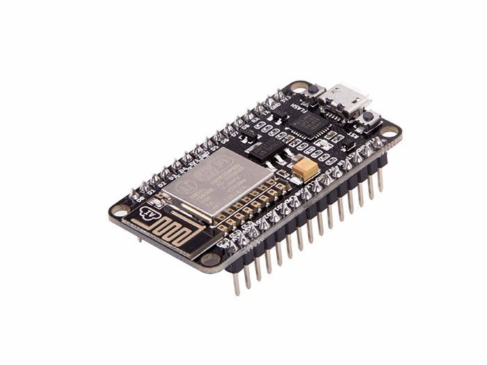
Keeping all that in mind I picked the esp8266, it has wifi, there are form factors with 3+ IO pins, it is cheap, and I have multiple of them just lying around, how convenient ![]() . You can get them from many places in many form factors, Sparkfun has loads. This is the form factor I am using:
. You can get them from many places in many form factors, Sparkfun has loads. This is the form factor I am using:
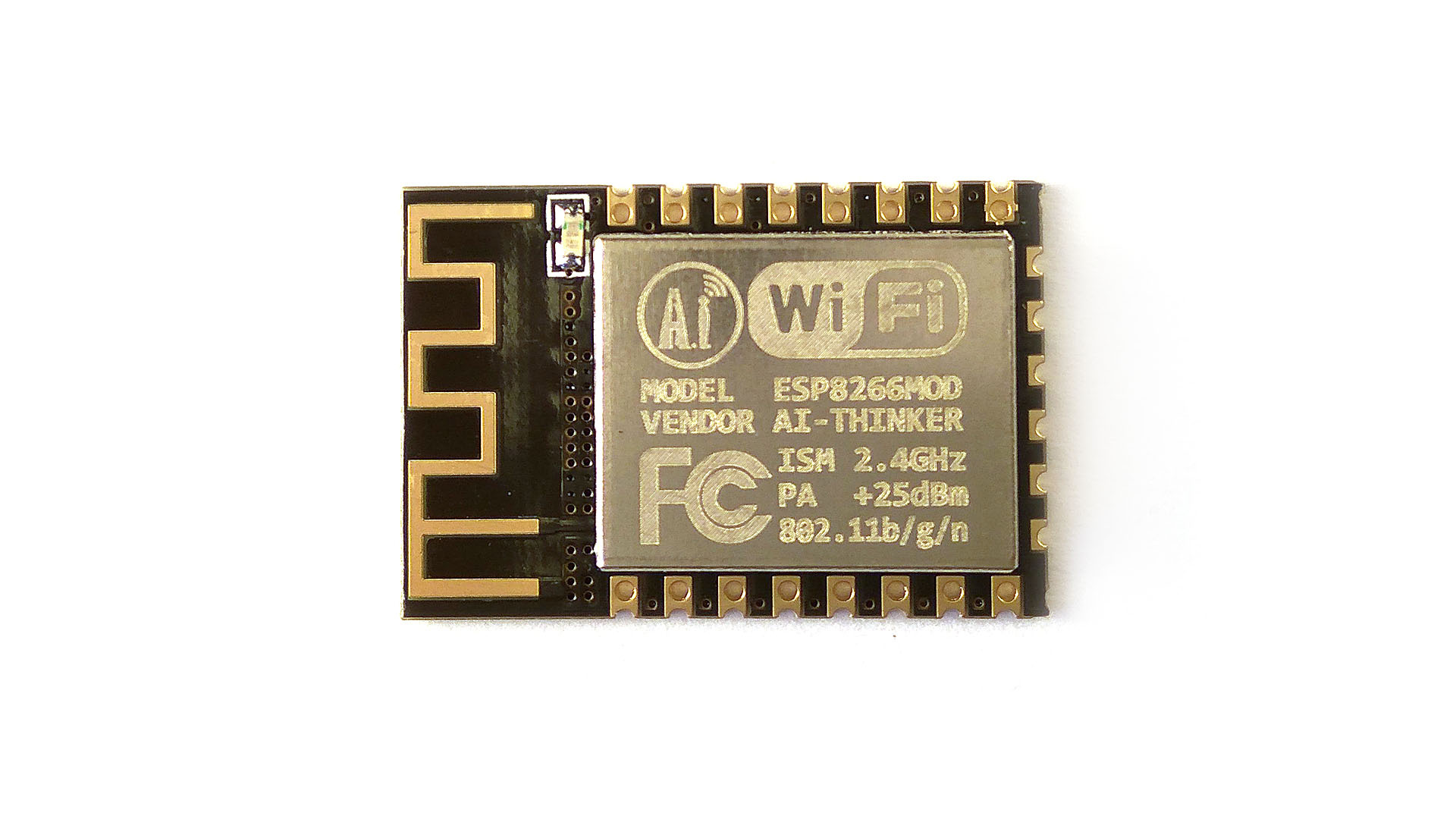
If I was to later make a custom PCB for this project I could simply get a esp8266 board without the breakout board like this:
One drawback of the esp8266 is it works on 3.3v logic not 5v like a lot of microcontrollers.
To get around this we could use a logic level converter like this which would let us use the IO pins as normal but since for this project at least I only intend to read from the Wiegand interface I will just make a voltage divider with some resistors. You also could just use the 5v, I have done it before and it works but it may have been pure luck and will likely shorten the lifespan of some components ![]() so I do not recommend it.
so I do not recommend it.
Introduction to Home Assistant and MQTT
Home assistant is what I use as the main interface point for all the different gadgets I have around my house and automation code I have running. I plan on using a MQTT broker that the Arduino will publish the ID of each card it reads which will then be checked against a list of valid cards and open my door. There are some cool things I will be doing like using rules to determine if I am coming home or leaving that I will also cover soon™ along with a more in depth overview of Home Assistant and MQTT ![]() .
.
Coding the Arduino
Most of this project will be code based. There are 3 distinct parts in my mind communicating with the reader, configuring the WiFI, and communicating with the MQTT broker. I tend to work on the parts in isolation so I can solve any issues with that part without having to worry about what part is broken, so there will be a POC (proof of concept) for the Weigand interface, for the Setup + WiFi, and for MQTT communication. After I have shown each part works then I will go on to integrating them into a final product.
Note this is not intended to be a coding tutorial, there are many good resources here that can help get you started. Having said that I do want this to be as clear as possible so I will try to explain things in lay-terms as much as possible, if something doesn’t make sense sing out in the comments ![]() . In Arduino code the text following
. In Arduino code the text following // is called a comment, these are used to explain what the code that comes after it is doing.
POC - Weigand
So I have my reader and an Arduino. I want to test to make sure the base concept is sound before I worry about trying to communicate the data back to my smart home system.
I have stacks of microcontroller boards (literally) so I picked one that uses 5v logic for simplicity sake when testing the reader.
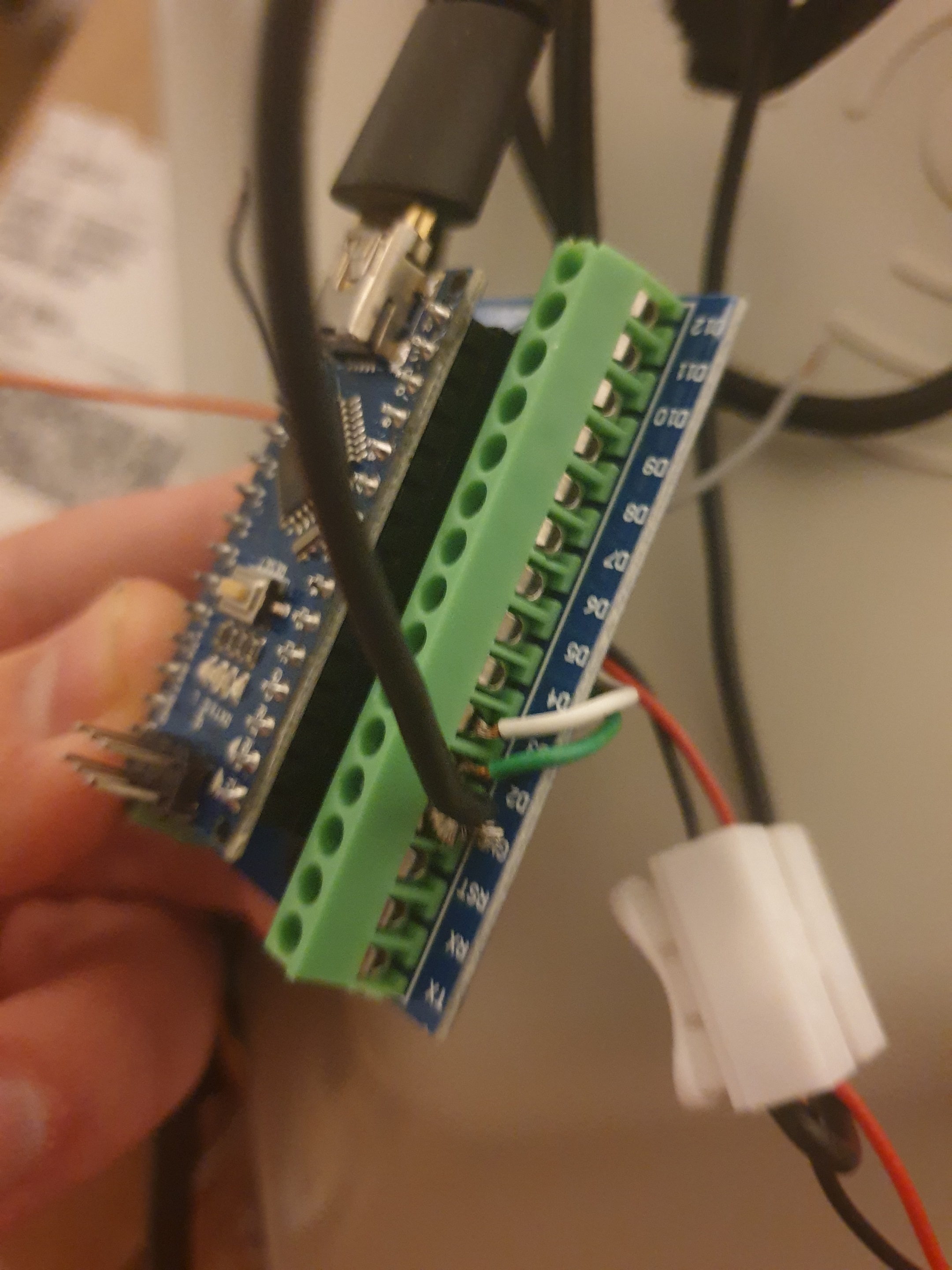
I hooked up the DATA0 and DATA1 pins of the reader to D2 and D3 on the Arduino respectively. I also bridged the grounds of the reader and Arduino, I did not need to add a power source for the Arduino as it was plugged into my computer and was getting its power over USB. The reader has a power cable that I plugged into the wall. Here’s a photo of my janky wiring:
I then looked for an Arduino Wiegand library, when developing software you usually can find premade packages of code known as libraries that you can reuse to speed up the development of your project.
I installed this that I found simply by searching for “Arduino Wiegand Library”.
I then followed the examples provided by the library and ended up with this sketch:
// Import the Wiegand Library
#include <Wiegand.h>
WIEGAND wg;

// This code is automatically run at startup
void setup() {
  // Open up a serial connection over USB to talk to the computer.
  Serial.begin(9600);
  // Open up communication with the reader.
  // I do not need to specify the pins I am using because the default pins are D2 and D3 so I am using them.
  wg.begin();
}

// This code is called repeatedly in a loop
void loop() {
  // Check that data has been sent from the reader
  if(wg.available()) {
    // Send the card info back to the computer so we can see if it is working
    Serial.print("Wiegand HEX = ");
    Serial.print(wg.getCode(),HEX);
    Serial.print(", DECIMAL = ");
    Serial.print(wg.getCode());
    Serial.print(", Type W");
    Serial.println(wg.getWiegandType());
  }
}
I then uploaded this to the board and opened the serial monitor tool in the Arduino IDE.
I scanned my card in front of the reader and this showed up on my serial monitor:
HEX = 442209, DECIMAL = 4465161, Type W26
This means it is working, in fact we could stop here this is a working Wiegand to USB Serial adapter but I do not want it to need to be plugged into a computer. In fact the reader worked very well I got 3-5 meters range using a flexible sticker tag
A note on the type, the library we used works with all the common Wiegand bit lengths so you do not need to change config for different readers.
POC - Setup + WiFi
Soon™
Here is the code for the WiFi setup portal:
//////////////////////////////////////////////////////////////////////////////
// Includes
//
// Here we select import the libraries we need for our project.

// JSON library for embedded C++
#include <ArduinoJson.h>

// ESP8266 File System Wrapper
#include <FS.h>

// ESP8266 WiFi Config and Communication Library
#include <ESP8266WiFi.h>
#include <DNSServer.h>
#include <ESP8266WebServer.h>
#define USE_AVAILABLE_PAGES false
#include <ESP_WiFiManager.h>

//////////////////////////////////////////////////////////////////////////////
// ESP8266 Pin Mapping
//
// Here we are defining a set of sensible names for the pins.
// None, not all of these pins will necessarily be used.

// D0 pin mapped to pin GPIO16/USER/WAKE.
#define PIN_D0 16
#define PIN_LED_2 16 // LED located near antenna.

// D1 pin mapped to pin GPIO5.
#define PIN_D1 5

// D2 pin mapped to pin GPIO4.
#define PIN_D2 4

// D3 pin mapped to pin GPIO0/FLASH.
#define PIN_D3 0
#define PIN_FLASH 0 // Flash button near USB port.

// D4 pin mapped to pin GPIO2/TXD1.
#define PIN_D4 2
#define PIN_LED_1 2 // LED located near USB port.

// D5 pin mapped to pin GPIO14/HSCLK.
#define PIN_D5 14

// D6 pin mapped to pin GPIO12/HMISO.
#define PIN_D6 12

// D7 pin mapped to pin GPIO13/RXD2/HMOSI.
#define PIN_D7 13

// D8 pin mapped to pin GPIO15/TXD2/HCS.
#define PIN_D8 15

// D9/RX pin mapped to pin GPIO3/RXD0.
#define PIN_D9 3
#define PIN_RX 3

// D10/TX pin mapped to pin GPIO1/TXD0.
#define PIN_D10 1
#define PIN_TX 1

// D11/SD2 pin mapped to pin GPIO9/SDD2.
#define PIN_D11 9
#define PIN_SD2 9

// D12/SD3 pin mapped to pin GPIO10/SDD3.
#define PIN_D12 10
#define PIN_SD3 10

//////////////////////////////////////////////////////////////////////////////
// Config

//////////////////////////////////////
// Config portal
//
// Here we define the details for the config portal

// The config network SSID
String config_ssid = "MQTT_WEIGAND_" + String(ESP.getChipId(), HEX);

// The config network password
#define CONFIG_PASSWORD "password"

// The pins for re-entering config mode after the initial config
const int CONFIG_TRIGGER_PIN = PIN_FLASH;
const int CONFIG_TRIGGER_PIN_2 = PIN_D7;

//////////////////////////////////////
// WLAN Connection
//
// Here we define the details for connecting to the wireless network.

#define WLAN_CONNECT_TIMEOUT 30000L
#define WLAN_POLL_DELAY 200L
#define WLAN_MAX_POLLS ( WLAN_CONNECT_TIMEOUT / ( 3 * WLAN_POLL_DELAY ))
String wlan_ssid;
String wlan_password;

//////////////////////////////////////
// MQTT
//
// Here we define the config parameters and there default values
// for the MQTT connection.

const char* CONFIG_FILE = "/config.json";
bool initial_config = false;

#define MQTT_Host_Label "MQTT Host"
char mqtt_host[64] = "";

#define MQTT_Port_Label "MQTT Port"
int mqtt_port = 1883;
char mqtt_port_string[5];

#define MQTT_Anonymous_Label "MQTT Anonymous"
bool mqtt_anonymous = false;

#define MQTT_User_Label "MQTT User"
char mqtt_user[32] = "";

#define MQTT_Password_Label "MQTT Password"
char mqtt_password[32] = "";

#define MQTT_Topic_Label "MQTT Topic"
char mqtt_topic[32] = "WEIGAND_READER";

//////////////////////////////////////////////////////////////////////////////
// Helper declaration
//
// Here we declare any useful defines and any helper functions we write in
// the "Helper Function Implementation" section that we need to use in the
// "Main Application Code" section.

bool load_config();
bool save_config();

#define BUTTON_DOWN LOW

//////////////////////////////////////////////////////////////////////////////
// Main Application Code
//
// Here we write the core application code.

// This code is run once when the microcontroller is powered on or reset.
void setup() {
  // Start serial communication for logging. Baud rate is 115200.
  Serial.begin(115200);
  Serial.println("\nSerial connection started...");
  // Setup trigger pins for button for input
  pinMode(CONFIG_TRIGGER_PIN, INPUT_PULLUP);
  pinMode(CONFIG_TRIGGER_PIN_2, INPUT_PULLUP);
  // Mount the filesystem
  SPIFFS.begin();
  // Load any previously saved config parameters
  load_config();
  // Configure WiFi manager
  ESP_WiFiManager wifi_manager("MQTT_WEIGAND");
  wifi_manager.setMinimumSignalQuality(-1);
  config_ssid.toUpperCase();
  // Load any previously saved WLAN details
  wlan_ssid = wifi_manager.WiFi_SSID();
  wlan_password = wifi_manager.WiFi_Pass();
  // Check if we need to start the config portal
  bool no_wlan_config = wlan_ssid == "";
  bool config_trigger_1_down = digitalRead(CONFIG_TRIGGER_PIN) == BUTTON_DOWN;
  bool config_trigger_2_down = digitalRead(CONFIG_TRIGGER_PIN_2) == BUTTON_DOWN;
  if (no_wlan_config || config_trigger_1_down || config_trigger_2_down) {
    // If the WLAN config is missing or the trigger buttons are held down
    // Print the config portal details to the serial console
    Serial.println("Entering config mode...");
    Serial.print("To configure connect to the '");
    Serial.print(config_ssid);
    Serial.print("' network with '");
    Serial.print(CONFIG_PASSWORD);
    Serial.println("' as the password and browse to '192.168.4.1' to configure this device.");
    // Configure additional config parameters
    ESP_WMParameter mqtt_host_parameter(MQTT_Host_Label, MQTT_Host_Label, mqtt_host, 64);
    ESP_WMParameter mqtt_user_parameter(MQTT_User_Label, MQTT_User_Label, mqtt_user, 32);
    ESP_WMParameter mqtt_password_parameter(MQTT_Password_Label, MQTT_Password_Label, mqtt_password, 32);
    ESP_WMParameter mqtt_topic_parameter(MQTT_Topic_Label, MQTT_Topic_Label, mqtt_topic, 32);
    sprintf(mqtt_port_string, "%d", mqtt_port);
    ESP_WMParameter mqtt_port_parameter(MQTT_Port_Label, MQTT_Port_Label, mqtt_port_string, 5);
    char mqtt_anonymous_html[24] = "type=\"checkbox\"";
    if (mqtt_anonymous) {
      strcat(mqtt_anonymous_html, " checked");
    }
    ESP_WMParameter mqtt_anonymous_parameter(MQTT_Anonymous_Label, MQTT_Anonymous_Label, "T", 2, mqtt_anonymous_html, WFM_LABEL_AFTER);
    ESP_WMParameter hint_parameter("<small>*Hint: if you want to reuse the currently active WiFi credentials, leave SSID and Password fields empty</small>");
    // Add additional config parameters to the WiFi manager
    wifi_manager.addParameter(&hint_parameter);
    wifi_manager.addParameter(&mqtt_host_parameter);
    wifi_manager.addParameter(&mqtt_port_parameter);
    wifi_manager.addParameter(&mqtt_topic_parameter);
    wifi_manager.addParameter(&mqtt_anonymous_parameter);
    wifi_manager.addParameter(&mqtt_user_parameter);
    wifi_manager.addParameter(&mqtt_password_parameter);
    // Start the config portal
    wifi_manager.startConfigPortal((const char *) config_ssid.c_str(), CONFIG_PASSWORD);
    // Get the newly configured parameter values
    strcpy(mqtt_host, mqtt_host_parameter.getValue());
    strcpy(mqtt_topic, mqtt_topic_parameter.getValue());
    strcpy(mqtt_user, mqtt_user_parameter.getValue());
    strcpy(mqtt_password, mqtt_password_parameter.getValue());
    mqtt_port = atoi(mqtt_port_parameter.getValue());
    mqtt_anonymous = (strncmp(mqtt_anonymous_parameter.getValue(), "T", 1) == 0);
    // Save the new config
  save_config();
  }
  // Store the time the that the microcontroller started trying to connect to the WLAN
  unsigned long wifi_started_at = millis();
  // Connect to WLAN
  while ((WiFi.status() != WL_CONNECTED) && (millis() - wifi_started_at < WLAN_CONNECT_TIMEOUT )) {
    Serial.print("Attempting to connect to ");
    Serial.print(wlan_ssid);
    // Try connect to WLAN
    WiFi.mode(WIFI_STA);
    WiFi.persistent (true);
    WiFi.begin(wlan_ssid.c_str(), wlan_password.c_str());
    // Check connection status
    int i = 0;
    while ((!WiFi.status() || WiFi.status() >= WL_DISCONNECTED) && i++ < WLAN_MAX_POLLS){
      Serial.print(".");
      delay(WLAN_POLL_DELAY);
    }
    Serial.println("");
  }
  // Print the connection results to the serial console
  Serial.print("After waiting ");
  Serial.print((millis() - wifi_started_at) / 1000);
  Serial.print(" secs more in setup(), connection result is ");
  if (WiFi.status() == WL_CONNECTED) {
    Serial.print("connected. Local IP: ");
    Serial.println(WiFi.localIP());
  } else {
    Serial.println(wifi_manager.getStatus(WiFi.status()));
  }
}

// This code is run repeatedly by the microcontroller after the setup function has finished.
void loop() {
  // Check trigger buttons
  if ((digitalRead(CONFIG_TRIGGER_PIN) == BUTTON_DOWN) || (digitalRead(CONFIG_TRIGGER_PIN_2) == BUTTON_DOWN)) {
  // If the trigger buttons are held down restart into config mode
    Serial.println("\nConfiguration portal requested. Restarting in config mode");
  // Restarting the device to go back to the setup function
  // By holding down this button while the device restarts it will force the config portal to start
    ESP.restart();
  }
  // Check WLAN connection
  // TODO
  // Read from Weigand
  // TODO
  // Publish to MQTT
  // TODO
}

//////////////////////////////////////////////////////////////////////////////
// Helper Function Implementation
//
// Here we implement the helper functions we declared in the "Helper function declaration".

// This code loads the previously saved config parameters from the config file.
bool load_config() {
  Serial.println("Loading config parameters from file...");
  // Open the config file in read only mode
  File f = SPIFFS.open(CONFIG_FILE, "r");
  if (f) {
    // If the config file opened successfully
    // Create an empty buffer object
    size_t size = f.size();
    std::unique_ptr<char[]> buf(new char[size + 1]);
    // Read in the raw data from the config file
    f.readBytes(buf.get(), size);
    // Close the config file
    f.close();
    // Create an empty JSON object for the config parameters
    DynamicJsonDocument json(1024);
    // Deserialize the raw config data into the config JSON object
    auto deserializeError = deserializeJson(json, buf.get());
    if (deserializeError) {
      Serial.println("Loading config parameters from file FAILED! Could not deserialize JSON.");
      return false;
    }
    // Print the config JSON object to the serial console
    Serial.println("Serialized config JSON:");
    serializeJsonPretty(json, Serial);
    // Load MQTT host from config JSON if a value has been saved.
    if (json.containsKey(MQTT_Host_Label)) {
      strcpy(mqtt_host, json[MQTT_Host_Label]);
    }
    // Load MQTT topic from config JSON if a value has been saved.
    if (json.containsKey(MQTT_Topic_Label)) {
      strcpy(mqtt_topic, json[MQTT_Topic_Label]);
    }
    // Load MQTT user from config JSON if a value has been saved.
    if (json.containsKey(MQTT_User_Label)) {
      strcpy(mqtt_user, json[MQTT_User_Label]);
    }
    // Load MQTT password from config JSON if a value has been saved.
    if (json.containsKey(MQTT_Password_Label)) {
      strcpy(mqtt_password, json[MQTT_Password_Label]);
    }
    // Load MQTT port from config JSON if a value has been saved.
    if (json.containsKey(MQTT_Port_Label)) {
      mqtt_port =json[MQTT_Port_Label];
    }
    // Load MQTT anonymous flag from config JSON if a value has been saved.
    if (json.containsKey(MQTT_Anonymous_Label)) {
      mqtt_anonymous = json[MQTT_Anonymous_Label];
    }
    Serial.println("Loaded config parameters from file!");
    return true;
  } else {
    // If the file failed to open
    Serial.println("Loading config parameters from file FAILED! Could not open config file.");
    return false;
  }
}

// Store the config parameters as JSON
bool save_config() {
  Serial.println("Saving config parameters to file...");
  // Open the config file in write mode
  File file = SPIFFS.open(CONFIG_FILE, "w");
  if (file) {
    // If the config file opened successfully
    // Create an empty JSON object for the config parameters
    DynamicJsonDocument json(1024);
    // Write the config parameters to the config JSON object
    json[MQTT_Host_Label] = mqtt_host;
    json[MQTT_Topic_Label] = mqtt_topic;
    json[MQTT_User_Label] = mqtt_user;
    json[MQTT_Password_Label] = mqtt_password;
    json[MQTT_Port_Label] = mqtt_port;
    json[MQTT_Anonymous_Label] = mqtt_anonymous;
    // Print the config JSON object to the serial console
    Serial.println("Serialized config JSON:");
    serializeJsonPretty(json, Serial);
    // Serialize the config JSON object into the config file
    serializeJson(json, file);
    // Close the config file
    file.close();
    Serial.println("Saved config parameters to file!");
    return true;
  } else {
    // If the file failed to open
    Serial.println("Saving config parameters to file FAILED! Could not open config file.");
    return false;
  }
}
POC - MQTT Communication
Soon™
Integrating the parts
Soon™
Wiring everything up
This section will cover the final wiring up of the circuit. When I get to this I will take photos and explain what I am doing but in the meantime here is a rough idea of how the wiring is going together.
The reader I am using takes 12v power. I will be using a DC to DC buck step down module to get a 3.3v output from the 12v. This will also cover the shared ground connection required by Wiegand.
Wiegand DATA0 will go to the D1 pin on the esp8266 and Wiegand DATA0 will go to the D2 pin on the esp8266 after going through a simple voltage divider with 2 resistors.
I will be adding a button eventually that I can mount on the enclosure to enter the WiFi config state but during prototyping I can use the D3 pin as it already has a button on the board hooked up to it.
Designing and Building an enclosure
I have a 3D printer so soon™ I will design and print a case for this project. This section will be less of an informative tutorial and more of a comedy where you can laugh at my abysmal 3D modeling “skills”.
Final Results
Once I have finished with this project I will post some updates on how it is working as well as a link to the git repo where the Arduino code lives, the STL files for the enclosure, the final BOM along with some photos and videos of it in use. This will also happen soon™.
Change log
2020/04/15 - Initial post
- Added introduction spiel
- Added the skeleton of the post
- Added introduction to Home Assistant and MQTT placeholder
- Added wiring everything up placeholder
- Added designing and building an enclosure placeholder
- Added final results placeholder
- Added project overview content
- Added introduction to Wiegand content
- Added reader options content
- Added introduction to Arduino content
- Added Arduino options content
- Added coding the Arduino content
- Added POC Weigand content
- Added this change log #Meta
2020/04/15 - Some clean-up
- Typos fixed
- Links fixed
- Added collapsible regions for ease of reading
[details=“2020/04/26 - Updated “POC - Setup + WiFi” content”]
- Added the POC of the WiFi config portal
[/details]