Hmm, depends on how you want to go about it. Are you sacrificing a remote or do you have wall mounted buttons you want to use?
2 Likes
Janky solution that could save you a remote is to use a motor to press the button on the remote ![]()
1 Like
That would still mean a remote permanently occupied. Unless your talking about a wall mounted remote in which case ther usually wired and are just dumb.
Even then if its a wireless wall mounted remote I still see no problem.
1 Like
Sorry should have been clearer. I was talking about not modifying a remote. I keep that stuff in mind as I rent so even if it’s reversible I wouldn’t risk my garage remote. ![]()
1 Like
Ahh I see. I mean you could definitely do it in a way that was non destructive and would not look suspect from outside the box.
But I mean yeah ofcourse you could use a servo with a little arm to press the buttons.
I never tend to think like that as the stuff I do is usually permanently fitted or atleast done in a way that can be detached and still work as “factory”
2 Likes
You maybe, but I am not so sure about me…

2 Likes
Pretty much any system is going to have a point of access. No matter how secure the communcations are, somewhere there is a button that you can push to activate it. That button pushes on a switch. A switch is nothing more than a connection that is opened or closed.
Regardless of how nice or getto you go about it, all you have to do is find the switch, and attach a wire to each side of it, then connect or disconnect as required via a relay controlled by the power of SCIENCE!!!
First law of ODaily, the first step to fixing anything is to break it so badly that it wants to be fixed.
4 Likes
Be good or the Toggleator will get you!!!
2 Likes
I have a wall mounted push button. I thought it was wirless but I took a look after I posted and it is the only thing in the garage that they actually ran wires through the wall for. So it looks like it’s just a normal push button opener. The only reasons it has a pcb inside is for it’s lock and learn functions.
4 Likes
Hey fellas… Couple questions…
-
can I use a regular 87 relay or do I need an 87A? I bought an 87 by not paying attention and the auto parts are all closed right now (11pm my time)
-
will this diode work?
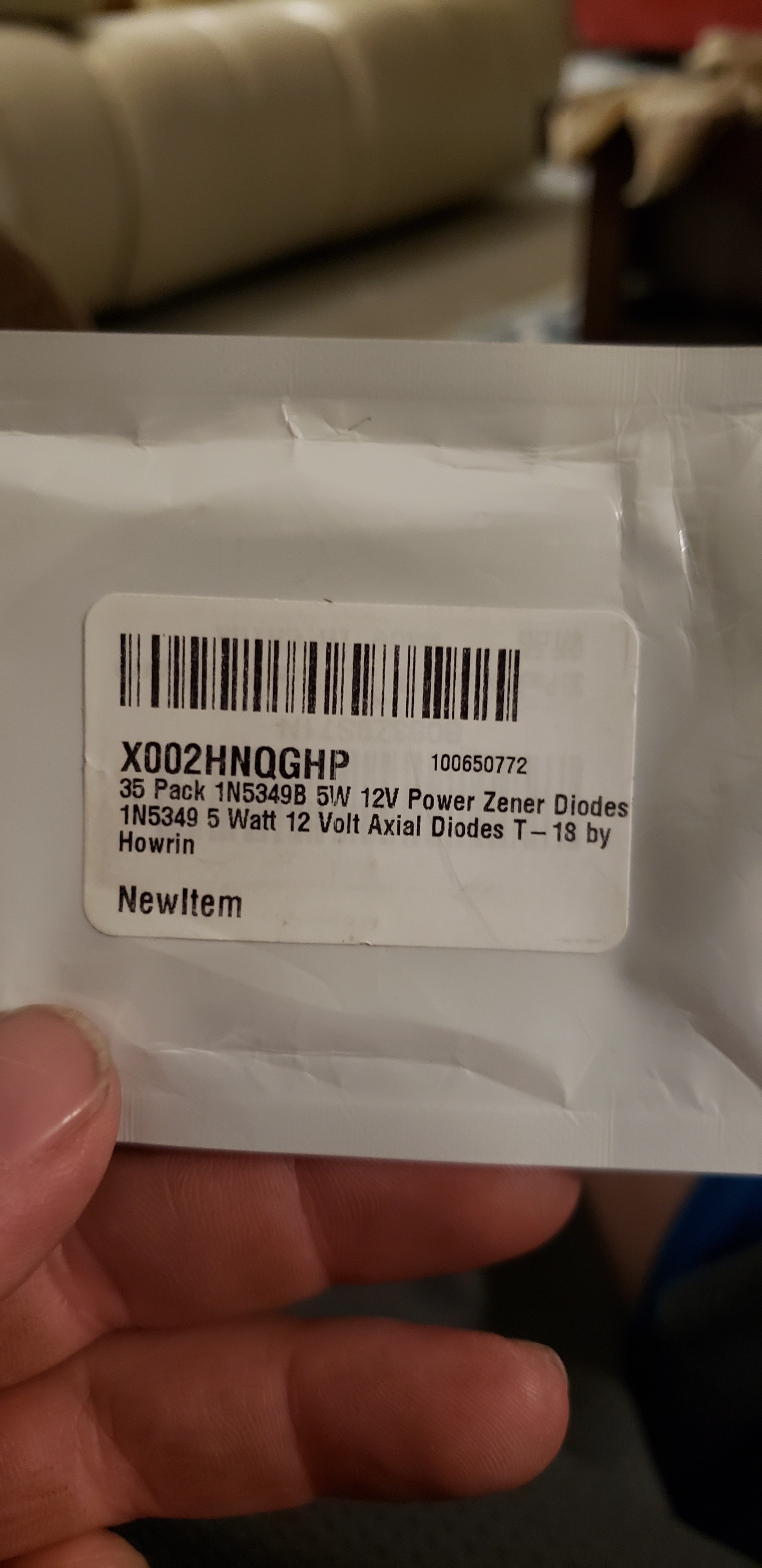
The controller is reading the tag, but garage door is not opening or closing… And my diode should be on my signal wire with the silver band towards the controller correct?
The band should be towards the relay. You can double check with a test light. Clamp it on the negative and test before AND after the diode. You should get light on both sides if it’s correct. If the light only works before the diode, then it’s backwards. Think of it this way, the power is SUPPOSED to go through to the relay, so hot on both sides, but if the power is coming from the relay (BAD) then it should be stopped by the diode. So only hot on one side.
This confuses me. The relay should have 4 or 5 terminals (connectors, or pins). They are all labeled. If you have a 5 pin, one of them will be labeled 87A, but you won’t actually use it. Assuming we are talking about the same thing, then the answer is the one you have is fine. This may help. Automotive Relay Guide | 12 Volt Planet
That diode will work fine.
About the Relay;
The terminals are labeled by numbers.
85 & 86 are the ones used to control the relay. One should be connected to ground. The other should be hooked to the white controller wire (with diode in between).
87 & 30 are connected when the relay is activated. You can hook them to the door circuit, or you can hook one to 12v and the other to something that will be turned on by that 12V
IF you use a capacitor, (this gives it a little time delay / hang time, but is NOT mandatory), then that get hooked between ground, and whichever terminal is hooked to the white wire. This should be between the diode and relay. So after the diode, but before the relay.
Also if you use an electrolytic capacitor, they can only be hooked up one way, the negative side is marked with a stripe on the side.
1 Like
I have a 4-pin relay… My garage door switch has two wires a red and a black. I have 12 volt positive to number 30. Ground to 85. Signal wire from controller (with diode) to 86. And my red wire from my garage door controller to pin number 87
It sounds like your diode is backwards, check that.
Remove the 12v positive from #30
Put the black wire from your garage door switch to the #30.
This makes the relay connect the red and black wires, just like if you pressed the switch.
EDIT:
Sorry late to the party “I replied” but didn’t press reply (oops ) @ODaily got your back anyway.
Oooohhhh, sounds like your project is moving ahead
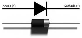
Diagram below I believe is back to front, I think of it like a valve, with the arrow(triangle) as the direction of flow and the Line is the valve blocking Voltage returning
You Diodes are 5W so at 12V that is just over 0.4A
Your Relay, I just depends on what you are trying to operate
87a is your Normally Closed (NC) terminal, so if all you need is Normally Open (NO) you will be fine.
FYI the12volt.com is a great resource.
Here is a link to relays
Relay Wiring Diagrams | the12volt.com
Flipped the diode and now the relay is clicking when the tag is scanned ![]() … but still no reaction by the garage door
… but still no reaction by the garage door ![]()
![]()
Almost there, just need to put the black switch wire to the #30 (and unhook the 12v that’s already there.)
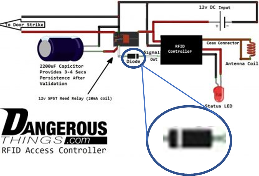
I think the diode in that Dangerous Things wiring picture is backwards.
Yeah, sorry, I should have put a note with that diagram, That was supposed to be what the picture above was for, Let me make that more clear
…
… Ok update… With my test light on the relay I can get it to light up when the tag is read… The garage is still not working ![]()