Willllll doooo ![]() . The wire runs up to my attic then along the beams where 2 walls are (roughly 22ft and 18ft ish), then down out of the attic lol. Lots of wire but makes it look super clean
. The wire runs up to my attic then along the beams where 2 walls are (roughly 22ft and 18ft ish), then down out of the attic lol. Lots of wire but makes it look super clean
Ok. I thought about this earlier and now I have to know if it would work. So I forgot I had an extra visor remote for my garage door. If I wired the xEM to one of the buttons wouldn’t it make it I wireless system. My only problem would be decreasing the voltage from 12v at the xEM to the remote board which uses a 3v battery. Wasn’t sure if I could just put in 2 resistors in series.


1 Like
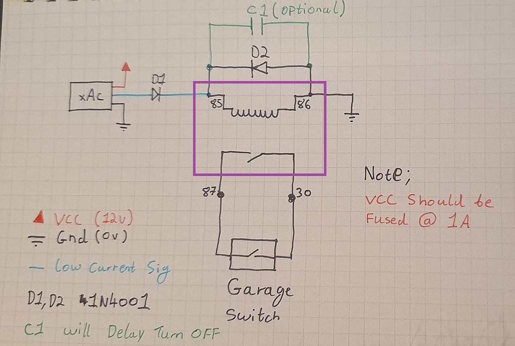
no that wont work, the issue is is the xAC gives out +12v when a valid tag is scanned. look at this diagram below the switch is the button in the remote, as for your 3v yes voltage divider tapped off the 12v (red wire) and feed that into the remote instead of the battery (make sure to remove it).
I also don’t understand the point of the 3rd resistor is in that voltage divider, it will work with 2 (10k and 3k3).
1 Like
Don’t really understand the 3rd resistor either its a screenshot from the electrodroid app I have. I was a little confused by your response. It looks like the board would be connected to the signal wire and to ground, but in your response you said the resistors should be added between the red wire and the ground. The 12v power supply goes the the xEM and then sends the signal to the board right? So I would remove the battery and wire the signal wire with the resistors in line and then another wire from the board to ground to complete the circuit.

Is that right or am I way off base. LOL thanks for the help.
No… don’t do this. I’ve explained this elsewhere, but basically you are going to burn shit out.
A button is a simple device. It shorts two contacts. That’s all. It’s literally just a piece of metal that you physically press down that shorts two conductors together. Typically speaking, the circuit designed to detect user interface button presses (basically all low voltage digital devices) has it’s own ideas about the electrons it wants to push down one of those conductors, and detect coming back in on the other conductor once the button is pressed (shorting them together).
Think of it like a toy train set… a big circle… and you’re there, cross-legged on Christmas morning, playing with your toy train set… and you have a little drawbridge in part of the track so imaginary sailboats can make their way through… and your drawbridge is up… so your train waits… well that drawbridge is the button. Once the button is pressed, the drawbridge is lowered and your little train of electrons can mozey on over the drawbridge and continue on their way.
Now let’s say your dad comes in with a hotwheels toy car track and glues it to the drawbridge and says “here come the cars motherfucker!” and instead of a tiny toy car making it’s way down the hotwheels track, he drives his 1967 Ford Mustang GT over you, your shitty little train track, the Christmas tree, and the dog. That’s what it’ll be like if you try to connect the access controller’s output wire directly to the button of your garage door remote.
So what’s the answer? A relay. A relay is what? It’s a device that shorts conductors together on command. Sounds kinda like a button right? That’s right, it is just like a button… only a button that you can control with another circuit! You connect a relay’s electromagnetic coil pins to the white output wire and GND of the access controller… when the output wire goes active, the relay’s coil will physically pull the contacts closed. Therefore, you solder the relay’s contact pins (the common pin and NO or “normally open” pin) to your garage door opener’s button conductors, and boom… you have an alternative, access controller controlled way to short the conductors of the button in your garage door remote… and you, the dog, your shittly little train track, and the Christmas tree all get to live (well, not the Chistmas tree, it’s already dead… just doesn’t know it yet).
15 Likes
I think this is one of my favourite posts on this entire forum. Educational and hilarious.
4 Likes
don’t forget to nominate it for BEST POST OF 2020!
5 Likes
Thanks man its all so clear now.

I need to let Rudolf the red-nosed relay guide my way…

Would that work? Just wire it the same as if I was wiring it to the button on the wall?
8 Likes

2 Likes
The 3rd resistor (RL) is an imaginary resistor representing the ESR of the load - usually calculated using the supply voltage and current draw. In the case of the remote, current used is tiny, therefore RL is so large as to be basically irrelevant and can be ignored.
Generally you want the current through the load to be an order of magnitude less than the current through R1+R2 (i.e. 10%) to keep the voltage stable under load. This just is a weird way to let you enter your expected current so it can change the voltage divider resistors to allow the right amount of current while keeping their ratio the same to maintain the voltage.
3 Likes
Yeah i spotted that after some sleep, it was early am.
@darkdragon885 yes thats what I was trying to get at, wire it exactly the same as a wall button.
For your 12v to 3v tap it off pretty much anywhen that is 12v permanent.
It didn’t seem like you to miss a trick like that! Thought I’d post the reply for the sake of prosperity and accurate archiving!
3 Likes
Got another question for you guys, since I have to buy the parts to do this anyway, would you suggest using an automotive relay or is there a cleaner way I can put this together?
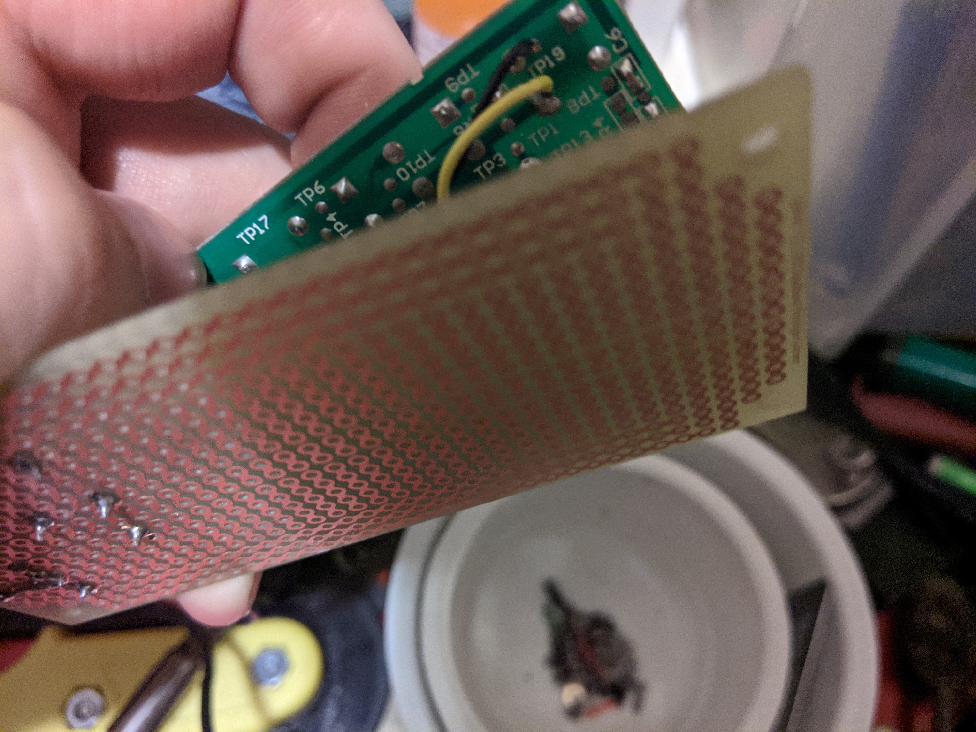
Can you solder? There are a number of small relays that have pins to solder into circuit boards. Plus you can get circuit boards that are just rows of holes. This also makes mounting diodes, etc, much easier.
But… for the circuit board, I’d try amazon. Better selection. For the relay, stay name brand.
1 Like
Thanks, I didn’t even think of using a blank board. Thats a great idea.
1 Like
Continuing the discussion from xEM access controller for garage door question:
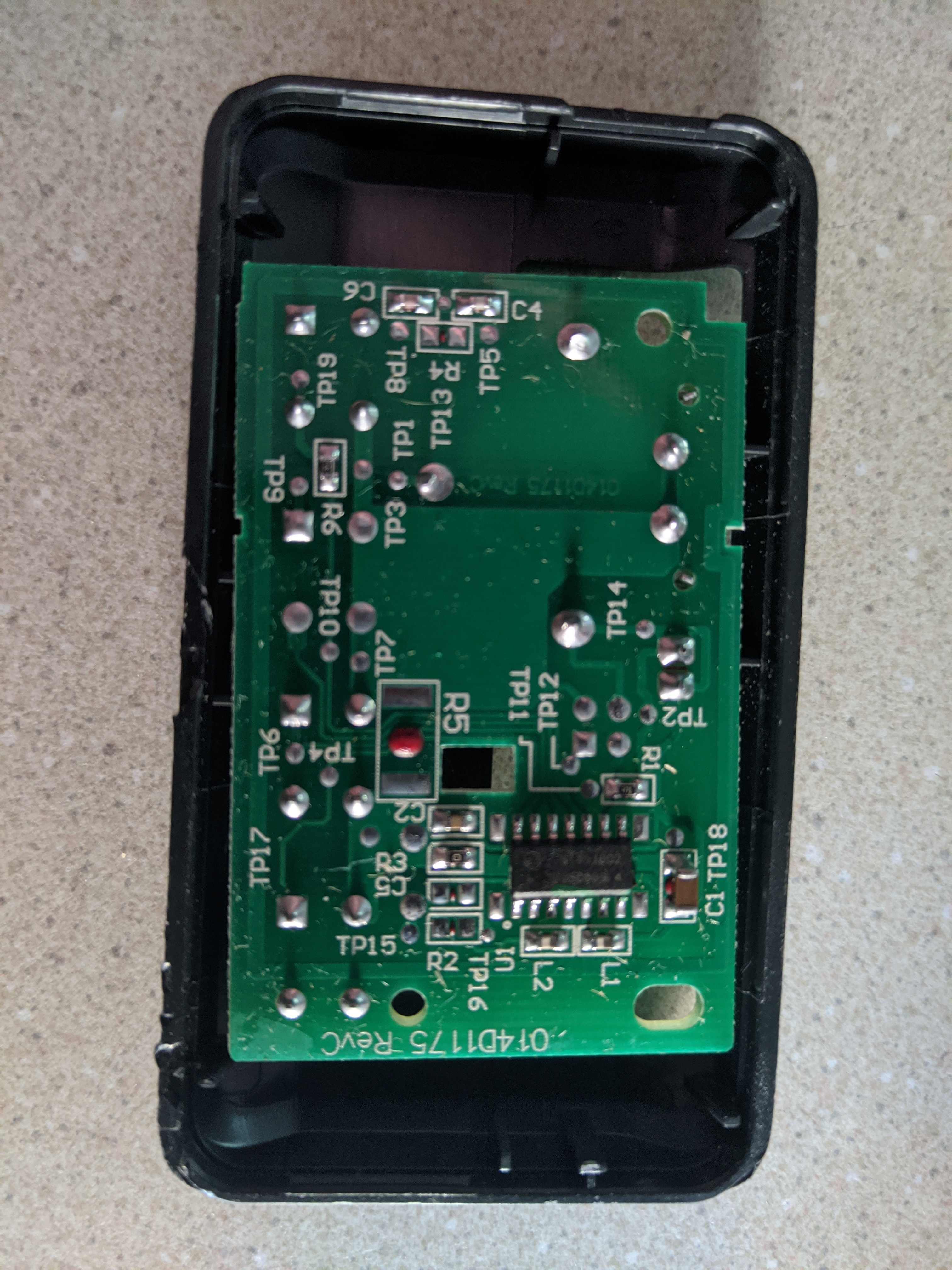
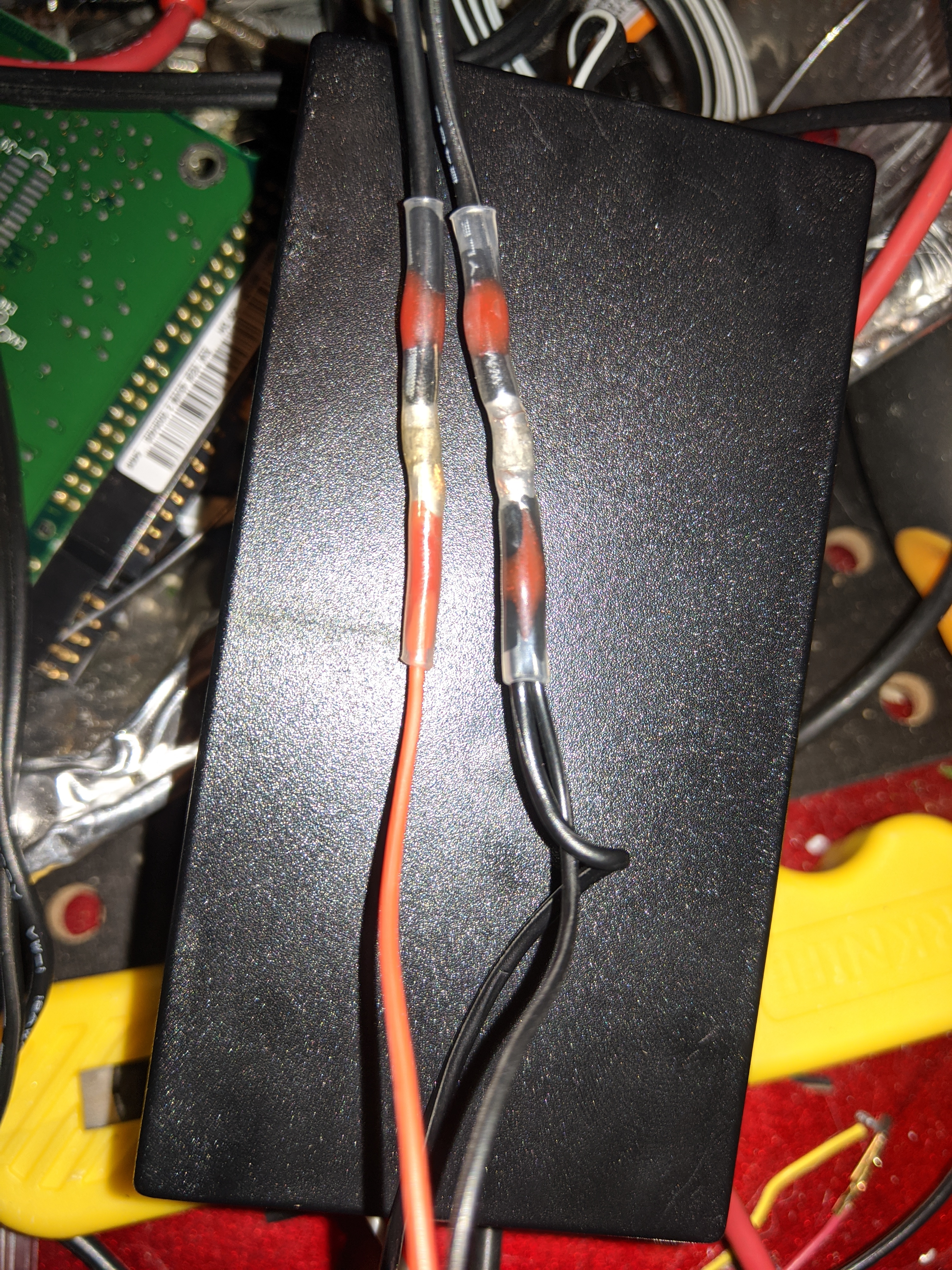
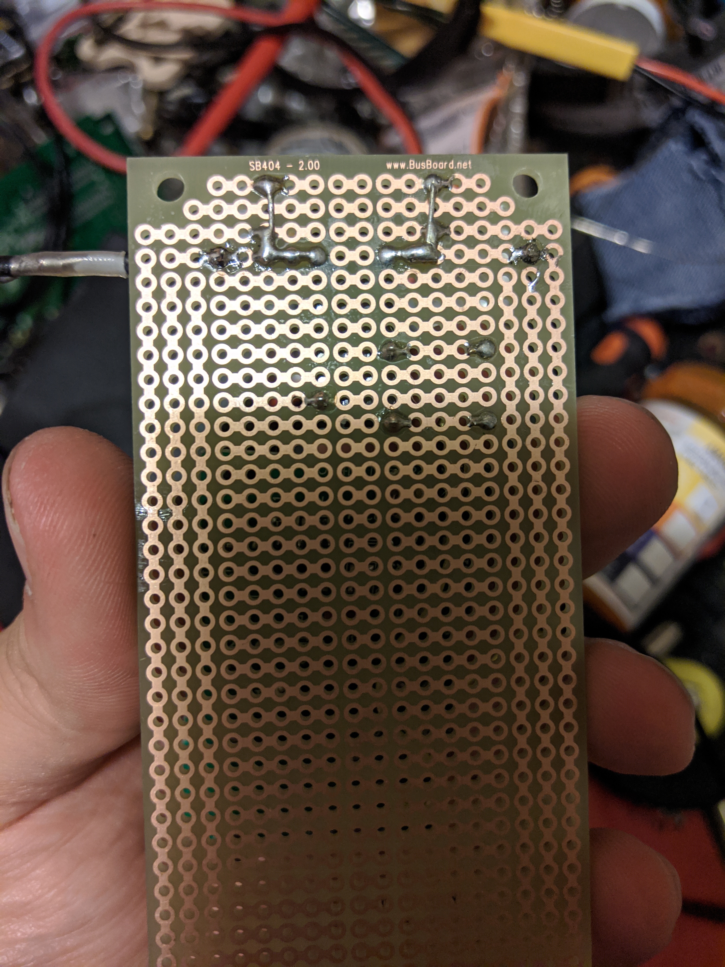
Ok here we go guys I feel like I am missing something obvious. I have a 12v power supply connected to my red and black wires of my xAC, the white signal wire has a diode in it and is connected to the board on the right, on the board I have my capacitor and diode connected to my 12v relay. The relay is a G5Q-14 and is 12v. It has 5 pins in the photo looking at the back of the board going clockwise om the data sheet the pins are 5, 1, 2, 3, 4. The coil is between 5 and 1, 2 and 3 are NO and I think 2 and 4 are the NC. So I have my signal wire attached to 5 and my ground to 1, I have the wires from 2 and 3 attached to the button on the controller. I get an intermittent relay click but it seems random. I’m so confused. Here are some photos not sure how well everything can be seen. Stupid question the black wire that splits one split goes to the xAC and the other goes to my bread board right? What the hell am I missing here?
1 Like
First of all… Sweet!
Next…
You have a system of sub systems. What you need to do is verify that each subsystem is working in the chain that makes up the greater system. I’m gonna have you check it all the way through. I know it’s kinda obvious, but we need to rule out each part in order.
Step 1. Verify you’ve got the actual power you’re supposed to have. Make sure it stays at a stable 12V while the access controller is active. All Good? Step 2.
Step 2. Need to verify that the access controller is getting a good clean repeatable read. It comes with a red LED on a wire for that purpose. Try reading it, and see if you’re getting the light to come on and stay on while reading. If it flickers or jumps around, you’re not getting a good read. Try enrolling one of the tags that came with it, you can usually just lay them on top of the antenna and it’ll stay on. If that works, step 3.
Step 3. Verify you’ve got good power and ground at the relay. Use an LED across the pins (WITH resistor!) or a multimeter. You should get good 12V power between pin 1 and 5. If that’s good, then step 4.
Step 4. Check for continuity between pin 2 and pin 3. It should be closed when the relay is powered. If that’s good, then the whole access controller circuit is working. It may be in how you’ve adapted the opener’s circuit. Try removing the wires from pin 2 and 3, and then touch them together. It should work the opener.
That should be good for now, and those tests are gonna reveal 99% of the problems. If everything checks out, we’ll try again for the weird 1% stuff.
2 Likes
ok I think it might be a problem with the way i have the remote wired I get 12v at the source but only 9.8v across pins 1 and 5, the relay clicks though. I tried to connect it straight to the wall outlet like the other guy on the post did but either I did something wrong or reversed my wires cause now my wall switch is blinking and wont work. Thats a problem for another day. The wireless remotes still work.
Sorry if this seems idiotic, but I was looking at the pictures and the remote clearly has a place for a battery, but no battery. I can think of lots of reasons why that might be, but with nothing working, I gotta ask, Does the remote circuit board have a supply of appropriate voltage power?
That is a great question. Devilclarke suggested I split off and reduce the voltage from the 12v power supply. But it looks like I missed that step. It was a 3v battery. Gonna have to see if I’ve got some resistors on hand. Any other way I can do it?