Hi all!
I recently installed the “xEM Access Controller v2” access kit to the door, everything works great with my “NExT” ![]() implant. In this system it is possible to set the relay delay fixedly to 1 second or 5 seconds.
implant. In this system it is possible to set the relay delay fixedly to 1 second or 5 seconds.
Friends, tell me how you can either increase the delay time from 1 second to 3 seconds (or reduce it from 5 seconds to 3 seconds).
I really need this intermediate value.
I’m good with a soldering iron, so if you need to add a capacitor or resistance to an electrical circuit, I can do it
I would be grateful for any help ![]()
You just change the one of the jumpers. This video isn’t updated for the v3 but it has the same jumper for relay timing…
Hi Amal, yes, I saw this video and studied in detail, but when changing the jumper from 1 second, the time suddenly changes to 5 seconds — and I want to get the intermediate one (about 3 seconds)
I’m even ready to solder the necessary electronic elements
Oh I see. That’s not possible. You could build a timer circuit yourself but that’s a bit advanced.
Could you:
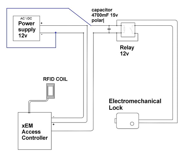
Use the xEM to power a 12v relay.
Add a capacitor in parallel to the relay. (with a value selected to give an extra 2 secs of “hang time”)
Analog, baby! Analog! ![]()
The version 1 was just on/off, and that’s how I got my hang time when I did my tool box.
Also, I don’t know what @AlexG is controlling with the xEM, but you might be able to omit the relay if the load is in a reasonable range relative to capacitor.
A capacitor is a good idea. As far as I understand, you need a polar capacitor above 12-14 volts - what is the approximate capacity? Can you tell me? ![]()
![]()
![]()
![]()
Well, you’d need a capacitor and a relay. The capacitor would be charged during the 1 second on time, and slowly discharge by keeping the relay engaged until it falls out. You need math. Fortunately, @Satur9 has already provided it.
To my regret, it is impossible to refuse to use the relay. since an electromechanical lock is connected through it to lock the door
Thank you very much for the information!
I’ll try it
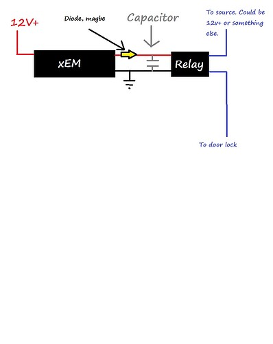
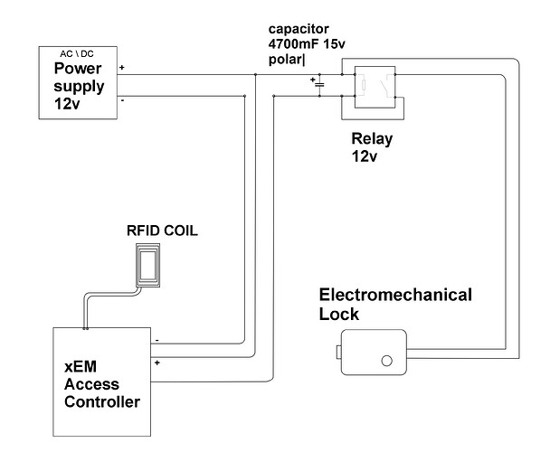
This is crude, but something like this, perhaps.
If that doesn’t work for you, then take a couple of pictures of your current setup and we can work from there.
Once I test the capacitor in action, I will definitely report the result. ![]()
![]()
![]()
You’ll probably need to try a few capacitor values to get the timing right, just fyi.
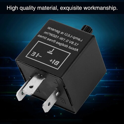
My solution would be an indicator (turn signal) relay.
You can adjust the time with the built in pot.
something like this
it clearly says
“High quality material, exquisite workmanship.”
So It must be good.
https://a.aliexpress.com/_mOrQ4M6
There are other options, including 2 pin variants
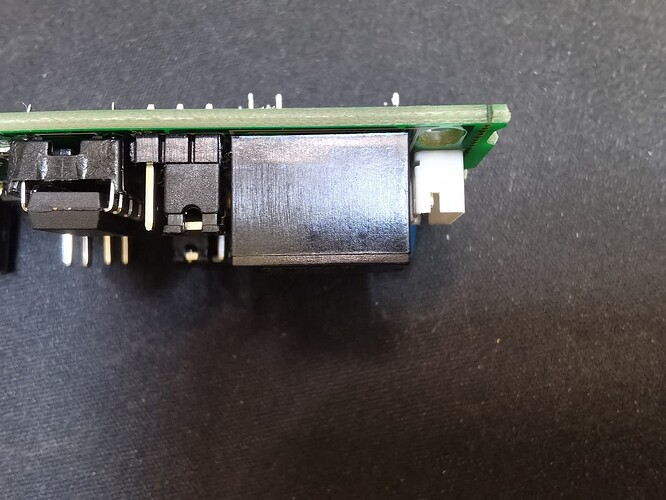
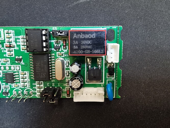
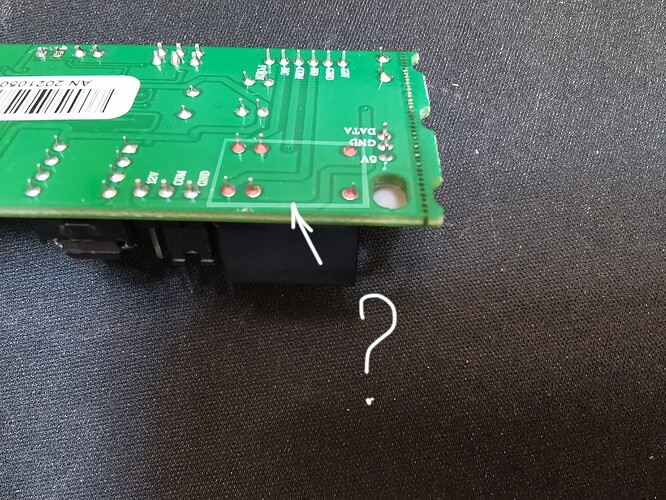
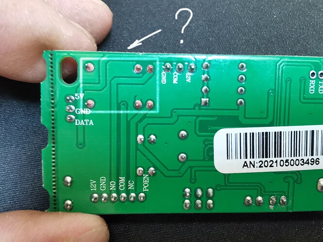
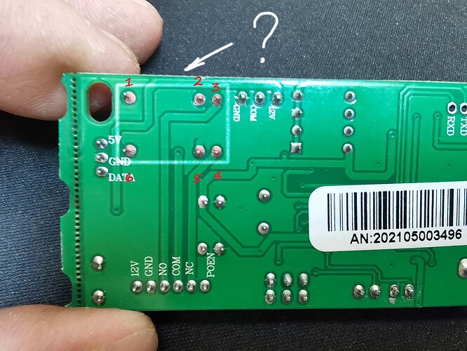
Hello, unfortunately I could not find a datasheet for this particular relay in order to understand where its power contacts are in order to solder the capacitor.
??
You could hook the output to an Arduino and hook that to another relay and control the timing that way
I’m way too lazy to work out changing circuits
Sorry, this kinda fell through the cracks on me.
- Common
- Coil
- NO
- NC
- Coil (grounded)
- Common
HOWEVER, I would strongly advise you not to put a capacitor directly on this relay. This was a known issue with the v1 boards that didn’t have a relay, when using an external relay. Basically, the cap could backfeed the circuit that charged it, and damage it. The solution was to add a diode to protect the V1 board from being backfed. Because I don’t know if the V2 board would suffer from the same problem, it’s a big risk. And there’s not really a good way to add a diode in the middle of the boards circuitry.
What I would recommend you do is:
Get an extra relay that is external to the board.
Turn the extra relay on with the relay that’s on the board, which will keep it isolated from the boards circuitry.
Put your timing capacitor across the coils of the second relay. It will be 2nd relay on (and charging the capacitor) for 1 second + however long the capacitor can hold the second relay open (while discharging capacitor).
Thank you very much for the necessary clarifications! ![]()
You’re running + power from the Power source to one side of your relay / cap, and + from the xEM. Two positives won’t work. I switched your diagram so that one side is ground (Negative).

