Bodybytes Implant

You’re an absolute god Satur9.

2 Likes

Jesus answered them, “Is it not written in your Law, ‘I have said you are “gods”’"

John 10:34 in case any Christian objects to such a description of a human.

3 Likes

LCR Measured inductance: 20.9uH
19.05uH VNA measured inductance

C1 = 1/((100000×2 π)^2×0.00001905)
C1 = 133nF

C2 = 1/((1000000×2 π)^2×0.00001905 - 1/(1.33×10^-7))
C2 = 1343pF

R = 1.3Ω

Q = (2 π×1000000×0.00001905)/1.3
Q = 92 (excellent, it needed to be higher than 77)

Fuck it was $45 for 2 Qi receiver chips because of the chip shortage
https://www.alibaba.com/product-detail/Integrated-Circuit-Power-management-Battery-management_1600435960353.html

k, ordered all the parts. It’ll probably be a month before they arrive

8 Likes

14 Likes

With help from @TallowyCape I was able to get gossa running on my VoCore completely OTA. It’s a pretty great utility. I was able to upload a 4.09MB file in 50 seconds from my pixel3a which I’m calculating out to 650kbps. It allows you to play stored videos with good quality and no stuttering. It got a little warm but totally manageable.

I just need to get it recognizing the SD Card and then I can upload a larger video and stress test the Qi charger powering it under load.

Since openWRT is a Linux distro, does anyone have any ideas about how we could run some kind of secure recovery sector in case the OS gets bricked or needs to be changed while you’re fucking around with the device? Like a BIOS or a bootloader. I’m not a software person.

5 Likes

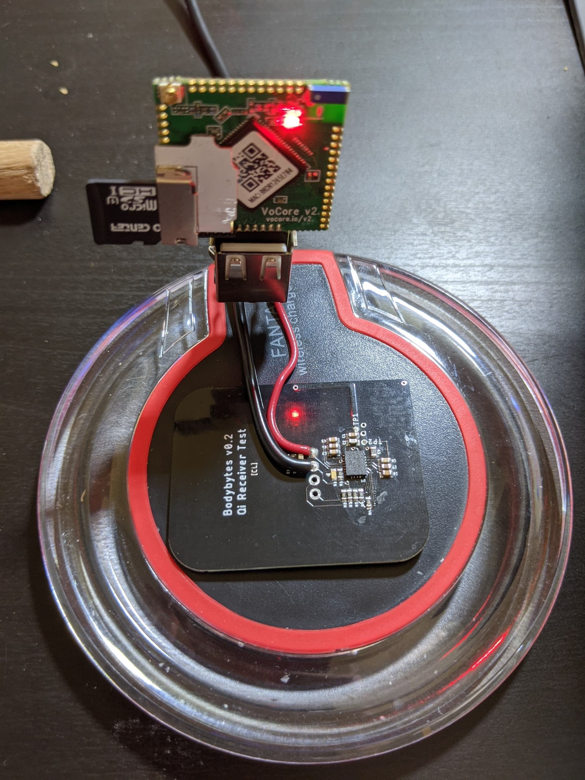
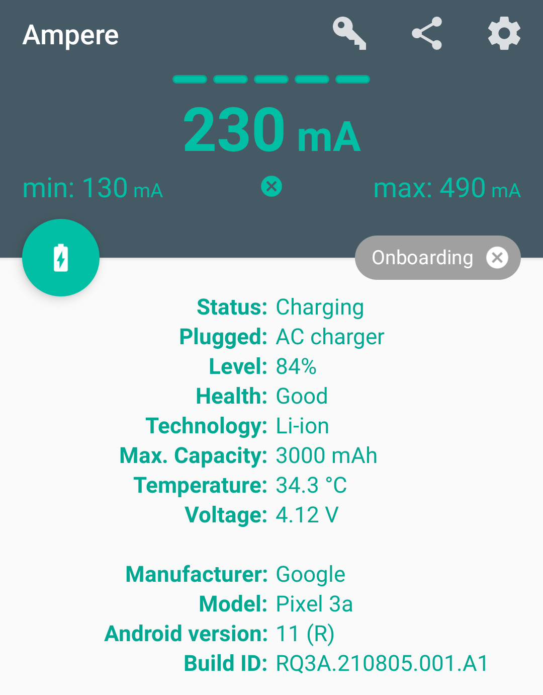
Not able to ssh in while it’s powered from the Qi charger. I used a battery monitor on my phone to see what kind of current the Qi charger is outputting. Here’s the conditions when I hook my phone up to a standard AC/DC adapter

Here’s the conditions when I hook it up to the Qi charger with a USB-A port attached

It looks like the current limit (which I had planned to be around 750mA) is actually turning out to be too low for the VoCore to get fully booted up. Maybe I can change the ILIM resistors (R4 and R5). Regardless the Qi receiver chip gets a bit warm. I’m not certain if having it inside the body will be good or bad for heat dissapation (I’m thinking good).

8 Likes

So I tested some stuff out. First I changed the R4 ILIM resistor from 330Ω to 140Ω. This would set the upper current limit to 1.07A (which I don’t think this antenna can achieve). The vocore still booted, was solid for 5 seconds, fast flash for 5 seconds, slow flash for 5 seconds, then it would soft reboot.

I then powered it from my power supply to investigate the power draw. Booting up peaked at 170mA and then settled at 120mA. It also didn’t go above 170mA while streaming video via gossa.

I then thought it might have been a thermal shutdown, because the chip was getting hot enough to hurt my fingertip. I immersed it in some oil which kept the chip very cool, but I still experienced the exact same soft reboot issue.

I then hooked a 1F supercapacitor up to the output and the vocore booted fully no problem. Looks like we need a bigger resevoir. I tried all the way us to 536uF and it still wasn’t enough. Now I’m going to look at what kind of capacitor bank I can make in a reasonable form factor. I’m thinking tantalum capacitors might do the trick. I’ll keep you posted.

7 Likes

These look nice. I’ll order a batch of these and just keep adding them until I find out how much is enough. Maybe I can map the transient response with an oscilloscope to get a rough estimate. I dunno though, with the power variability caused by the positioning of the Qi coil I might be SOL on predicting any of the behavior. We’ll just have to leave plenty of headroom.

https://www.digikey.com/en/products/detail/kyocera-avx/F980J107MMAAXE/5957626

6 Likes

I tried 5mF of capacitance and that wasn’t enough for the vocore to boot. I could maybe fit 180 of those 100uF tantalum caps, which would be 18mF. It would be tight and expensive though. They’re 0.38USD at MOQ 100. That also still might not allow the vocore to boot. There’s also the equivalent series resistance to consider, which is lower for the standard can electrolytics I was testing with then it would be for the SMT tantalums (although neither would be as high as the supercapacitor). We have several options here:

  1. Use one or more SMT supercaps and abandon any hope of encapsulating the bodybytes in flex biopolymer (which I would very much like to use)
  2. Make the total surface area larger and include more SMT caps (which would require a slight antenna redesign)
  3. Select a different processor that has less power demand
  4. Preload the vocore with firmware that has a low-power bootup so that it eliminates the brown-out condition we’re experiencing now

I won’t pretend to work understand a fraction of that

But… are capacitors a safe idea subdermally?

You know far more than I on these components,… but all I can picture is a capacitor blowing…

I’ve only wrecked a few pcb components… no caps thankfully… but even then none of those were events I would like to reproduce inside me :-/

Ceramic and tantalum capacitors have solid dielectrics so barring a serious ESD issue where they physically burn, they’re safe during power cycling. Electrolytic “can” capacitors have liquid elecrolyte and can build up pressure and burst. Depending on the formulation, that dielectric can be ionic or even caustic, so I’d rather avoid using those (which works out because they’re awkwardly tall anyway).

The issue where there’s a bit of ambiguity is the supercapacitors. They are also in a can, and some have liquid electrolytes and can offgas (usually small amounts of liberated hydrogen). That’s not good and I don’t think we should use those. Considering that supercapacitors are a constantly evolving area of technology, there’s some leeway though. We could locate some solid state supercapacitors that will not offgas, but with the supply chain in it’s current state that moderately difficult proposition becomes nigh impossible.

Does anyone know how they resolved this in the pegleg, or was the Pi Zero just better optimized for low power bootup?

1 Like

Tantalum caps sound like a bad idea since even though they got a solid electrolite i’ve seen quite a few go frag with a bang just by looking at them wrong. Also have you measured the voltage on the cap array while bootup yet? I’m curious how the discharge courve looks. Also maybe the tdk ceracharge solid state batteries could work in combination with ceramic capacitors. I’m not sure if the current they can provide is enough thpugh… Mouser seems to have them but they are quite expensive… i like this project quite alot so far though. I’ll think a bit if i can come up with something to help here

2 Likes

Someone else asked to see that as well. I’ll try and get on it this week. I should also publish the board files and BOM. I was hesitant because it wasn’t fully tested, but I’m more confident now and others could use this design. I will be doing a revision to test out energy storage, but I’ll just separate the revisions in different directories in a GitHub or some such.

I think you’re talking about these which are 84USD for 10 units. They’re 4.4 x 3 x 1.1mm. That can store 100uAh and supply 20uA continuously. They’re only 1.5V so they would have to be a 3S configuration. Not sure how that will behave. I’ll do some math later and figure out more.

Tangential I reached out to Cassox about something else and brought up this project. I’m hoping he can get us in contact with the peg leg v3 crew

2 Likes

Now that the chip shortage has calmed down a bit and the BQ51013 are back in stock domestically, I’m planning to make some other form factor Qi receivers for LED projects. I still want to work on this project more but it seems like we’re at a pivot point with the controller. Tallowycape, leumas95 and I are weighing the pros and cons of an ESP32 variant, sacrificing performance for reliability. That’s on the horizon though.

For now I wanted to share the Qi receiver PCB design as is. It could definitely use a bit of cleaning up if you’re intending to use it for any real application (remove the bodybytes specific silk and document layer markings, and maybe switch from 0603 passives to 0402), but it works pretty well as is. You can expect to source 250mA easily with this design. Feel free to use and modify it for whatever purposes you see fit. I don’t care if you credit me.

See this post earlier in the thread for C1 and C2 capacitor values:

QiReceiver[SCH].pdf (46.3 KB)

QiReceiverPCBFiles[bq51013a].zip (14.3 KB)

2 Likes

I will say the esp32c3 is a crazy tiny and powerful chip like these boards can be tiny tiny and are easy to develop with. I use them for a few projects. Adafruit QT Py ESP32-C3 WiFi Dev Board with STEMMA QT : ID 5405 : $9.95 : Adafruit Industries, Unique & fun DIY electronics and kits

2 Likes

Do you think you could run a simple file server on it?

https://docs.espressif.com/projects/esp-idf/en/latest/esp32c3/api-reference/storage/spiffs.html

I wouldnt use spiffs use littlefs instead.

And an example of using it for a web server

2 Likes

Wild to read all this, love the project idea. Would it be accurate to say that the current state is reflected in the OP, with time of researchers being the current limit?

I was following some of the experimentation of trying to get some capacitors to work… Most of it was well over my head so I kept my nose out of it lol

But getting enough performance out of small enough and “safe” enough components seemed to be a legitimate struggle… let alone source them