DIY LF antenna for Proxmark 3 Easy

An antenna within a uH of the target should operate on any proxmark easy. They do have minor manufacturing differences. Ultimately though it’s not like a passive RFID tag where the component values determine the tuning range. The Proxmark outputs a 13.56MHz signal no matter what. The difference between antennas that causes that voltage difference that Zwack mentioned, and the need for a resistor “sometimes” is due to the impedance of the antenna.

Impedance is just like resistance, but it adds a bit for the resistance of capacitors and inductors. Those values (reactance) change with frequency. Luckily we’re always at 13.56MHz in this situation, so it doesn’t vary. For the stock proxmark antenna they select an inductance value given the available antenna dimensions which “adds” resistance, and capacitance values which “subtract” resistance.

They don’t usually add actual resistors, because that limits the wattage of the antenna. What they usually do is if the impedance is too low (which causes the voltage to be too high) they’ll use thinner gauge wire which inherently has more resistance. Skin effect

Ok, it’s starting to come into focus a bit…

So then is there an advantage of using on size wire over another in this situation? Or should I maybe get slightly thinner wire to start with?

Too thin of a wire and you’ll get too high of a resistance … And there isn’t much you can do at this point …
A bit too big and you can add a resistance …

I used 30awg and don’t need a resistance at all, made a second antenna to confirm and have the same results …

1 Like

Weird, I thought @Compgeek used .25mm enamel wire which comes out to 30awg unless I missed something obvious

And he seemed to have high voltage

Weird but I guess I’ll order 30 awg and hope for the best

So to confirm, should I or should I not actually order an lcr meter? A few mentioned it’s use, but it looks like people where just adjusting based on what the proxmark said anyways

Thoughts?

That’s why I went with 30awg … But both of my antenna come up to between 24 and 28 volts, so I call that good enough … And get much better reads …

Well … I have one but didn’t used it for this …
Buuuuttttt … It’s a good tool to have on hand if you’re working with any kind of electronic, so maybe get one at some point …

Personally I don’t end up using my LCR meter for anything 13.56MHz because the Henry and Farad values are so small at this frequency range and it’s not accurate enough. I end up using my VNA for everything. You shouldn’t need that though, if the Proxmark reads too high a voltage just add turns. Too low subtract

3 Likes

Did you wind up going with 8mm rod instead of compgeeks 9mm?
(I think I’m looking at the same listing your might have ordered… given the number and lengths)

Could that be why you have better voltages?
Caveman thinking hard noises
Thinner core, the less it increases inductance or whatever… so you need more wraps… and longer wire… more resistance so better voltage?

Different ferrites have very different properties, and nobody has any fucking clue what “relative permeability” is so distributors just say “it’s ferrite!”. Compgeek probably ordered a lower permeability ferrite, which means the inductance was lower, which means the inductance’s contribution to the impedance was lower, which means more voltage perceived by the Proxmark

This sounds strangely familiar to a lot of non rfid stuff I deal with…

Lol

So just order something… wind it and see what the proxmark says is what I’m hearing?

Unless you want to go to great length to measure the properties, just try and make it like compgeeks and see what happens. Now you know what changes would tweak it, so you can adjust the coil once you have a reference point

1 Like

The ones I got are 8mm/0.3" OD
They clearly have no idea what it is … The description is actually pretty funny:

Description

Description

Specification:
Material: MnZn-ferrite
Diameter: 8mm/0.3’’
Length: 50mm/2’’
Use for Antennas
Quantity: 10pcs

Feature:
Ferrite rod material with flattened profile, for medium and high frequency circuit, antenna
Suitable for Crystal Radio,transformer,etc.
May be cut to size as required.

Application range:
Widely used in color TV, cell phones, monitors, electric vehicle charger, alarm, DVD, switch power supply, power up, DC-DC converter, high-frequency transformer, filter, inductor, household appliances, industrial automation, instrumentation, communication, medical equipment, energy saving lamps and lanterns and so on.
Package Include:
10pcs x Ferrite Rod

Notice:
1.Please allow 1-3mm error due to manual measurement. Pls make sure you do not mind before you bid.
2.The color may have different as the difference display,pls understand.

Ps: I’m not sure how to do the fancy fold down … Clearly used the wrong thing …

Thanks:

Cart before the horse I’m sure…

But is there anything drastic I’m missing at the idea of making a coil for the HF antenna?
Currently very disappointed in hf performance, more so than stock lf

I get that it’s a pcb trace, and harder to attach
But I was thinking breaking the trace right before it goes into the coil, and soldering on coil leads?

Just my caveman brain thinking

You select the big block of text and then from the gear icon choose hide details…

Like this

Description

Specification:
Material: MnZn-ferrite
Diameter: 8mm/0.3’’
Length: 50mm/2’’
Use for Antennas
Quantity: 10pcs

Feature:
Ferrite rod material with flattened profile, for medium and high frequency circuit, antenna
Suitable for Crystal Radio,transformer,etc.
May be cut to size as required.

Application range:
Widely used in color TV, cell phones, monitors, electric vehicle charger, alarm, DVD, switch power supply, power up, DC-DC converter, high-frequency transformer, filter, inductor, household appliances, industrial automation, instrumentation, communication, medical equipment, energy saving lamps and lanterns and so on.
Package Include:
10pcs x Ferrite Rod

Notice:
1.Please allow 1-3mm error due to manual measurement. Pls make sure you do not mind before you bid.
2.The color may have different as the difference display,pls understand

.

That’s exactly how to go at it :+1:

Ps: Caveman brand is best :brain:!

One more LF antenna, and 2 more in the way (one for a member here and the other to test with a wire between the PM3 and the antenna)

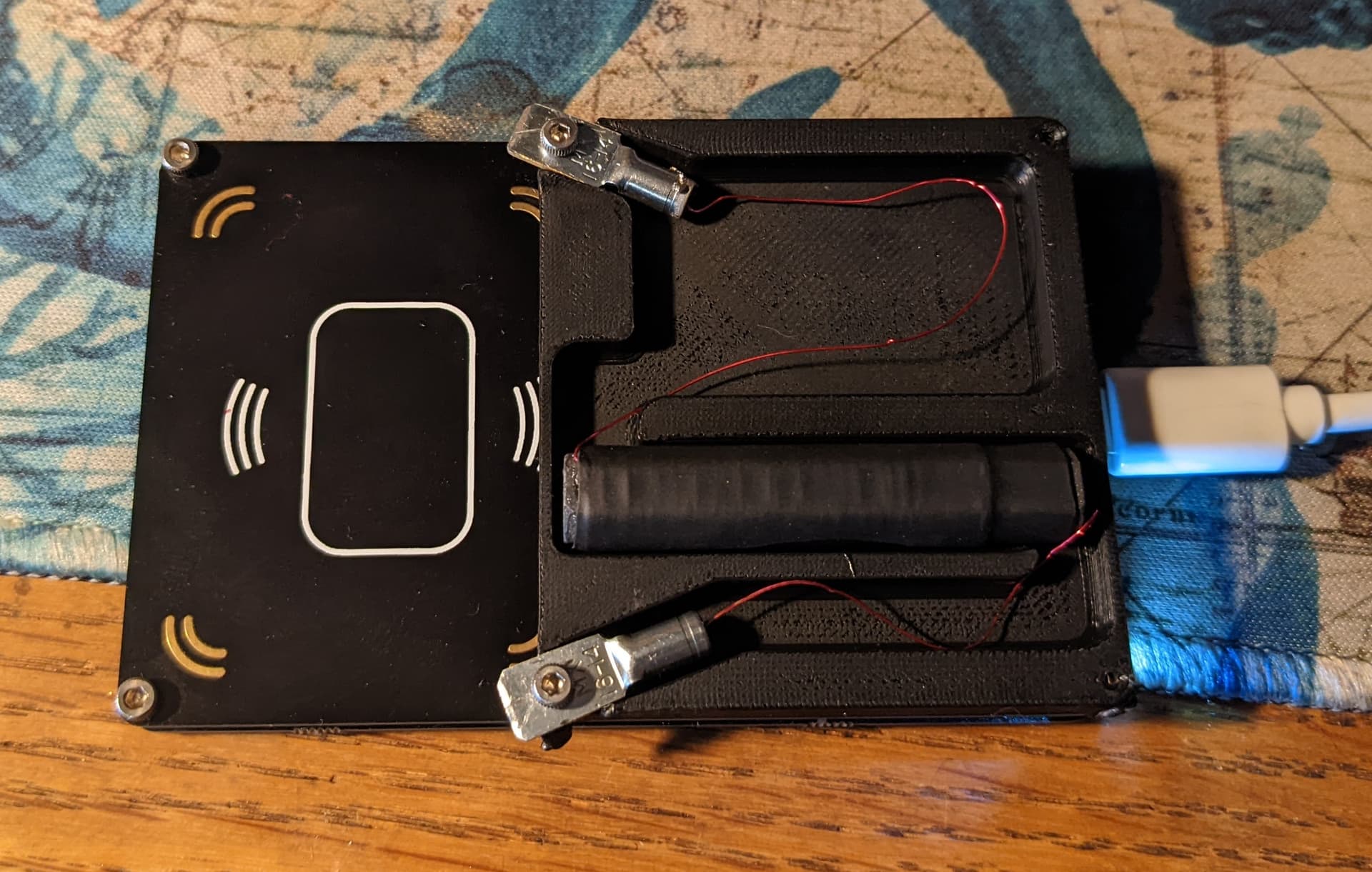
Ps: there will be a cover to hide all the wires, and the “pocket” is to put resistors if needed)

Here it is finished:

PS: Well, used it on the field today and it performed great, read the NExT instantly and flawlessly.
This is really the best thing you can do to your PM3 if you have a glassy …

3 Likes

Are you sharing the stl? I would love one

Sure can, I’ll post it tonight.
It’s not perfect, but more than functional (just used again today on the field)

I also designed some PCB to do that job, but cleaner …
It shipped yesterday, so I should have them shortly to give them a go.

Ha, I see you have already found this thread yourself, Nice :+1:

( I just linked to this thread your other post if you are wondering what the fuck I am talking about )

From proof of concept:

to rev.0:
(please excuse the gient wire on top, i think they messed a connection on the trace …)
image

And here is my first ever PCB:
image

Well, found the problem:
image

1 Like