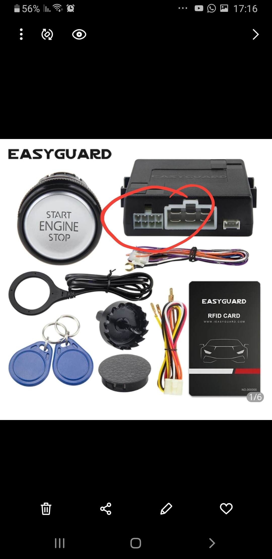
Easy Guard install
* There are others with different names, or different wiring colours, but the principle remains the same
One more use of the mighty T5577
I put an Easy Guard Push to start system in my car around 2 years ago, it has worked flawlessly, I also have a test rig on a bench and just yesterday I put another one into somebody elses car, so I documented it incase it could be of use to somebody else out there.
The main consideration / benefit of this install is that it is easily removable with the ability to return your vehicle back “to factory”
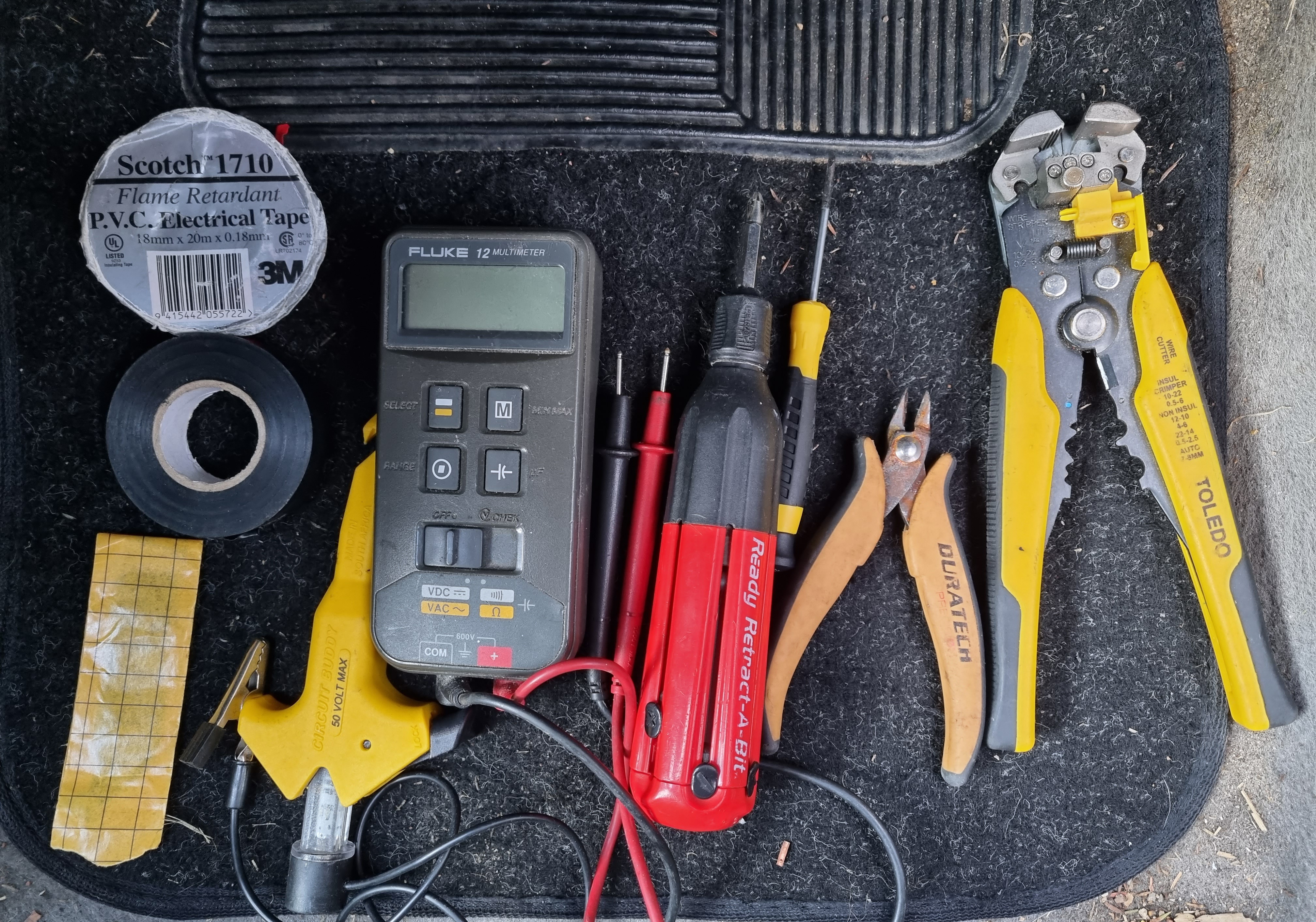
Parts, Materials, Tools and implants
There are many makes and models of cars so tools may vary, but here is a basic list
-
Pen paper / Phone ( for recording wiring colours )

-
Camera / torch ( Flashlight )

-
Multimeter, voltage tester
-
Electrical Tape : Red / black
-
Strippers

-
Ring terminal and crimp tool
-
Screw driver
-
Side cutters
-
Black tack (3M product, ~super tacky putty)
-
Scissors
 (For cutting tape, better than stretching to break)
Works with
Build Time
Will vary wildly, depending on the car
Mine took me ~45mins
Installation
There are many approaches you can use, below is HOW I DID MINE
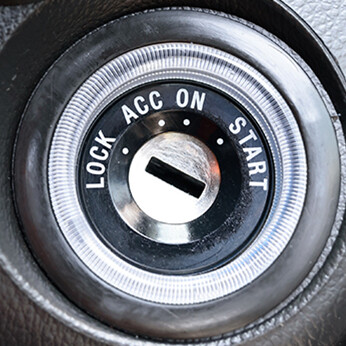
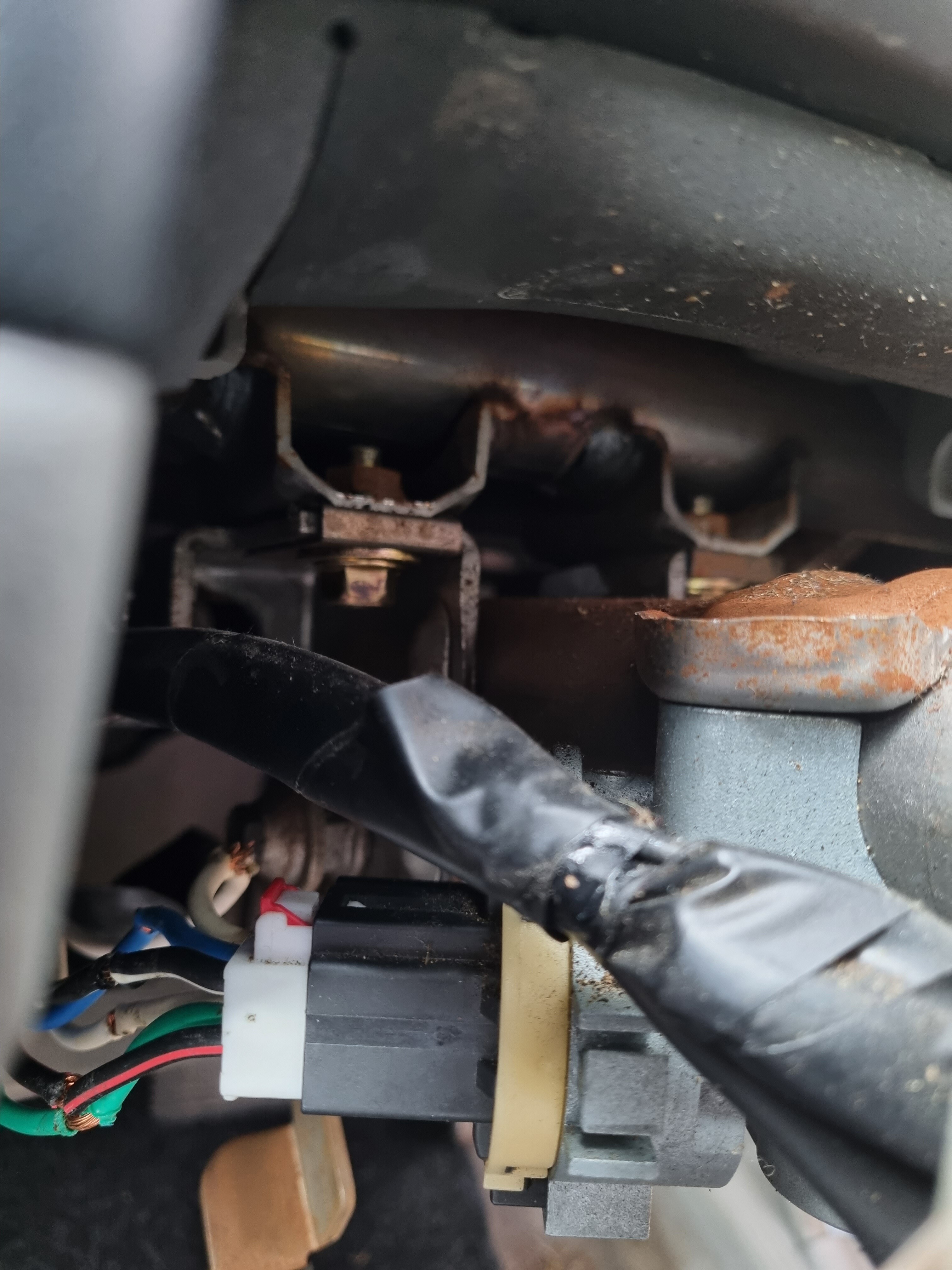
1. Access Wiring
In order to install, you need to get access to the ignition wiring, generally this is going to be in the form of removing a steering shroud or boss.
VIEW FROM BELOW
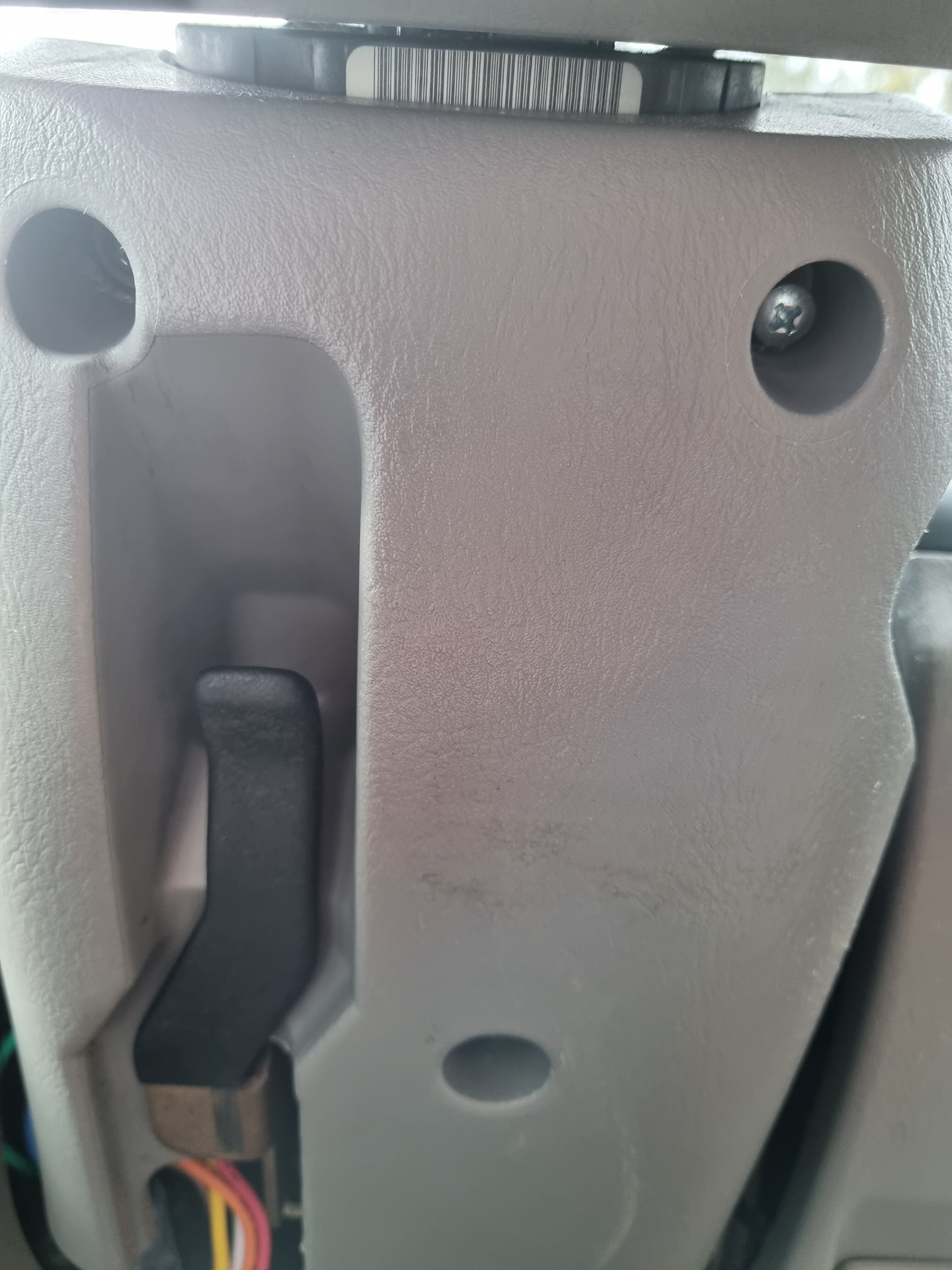
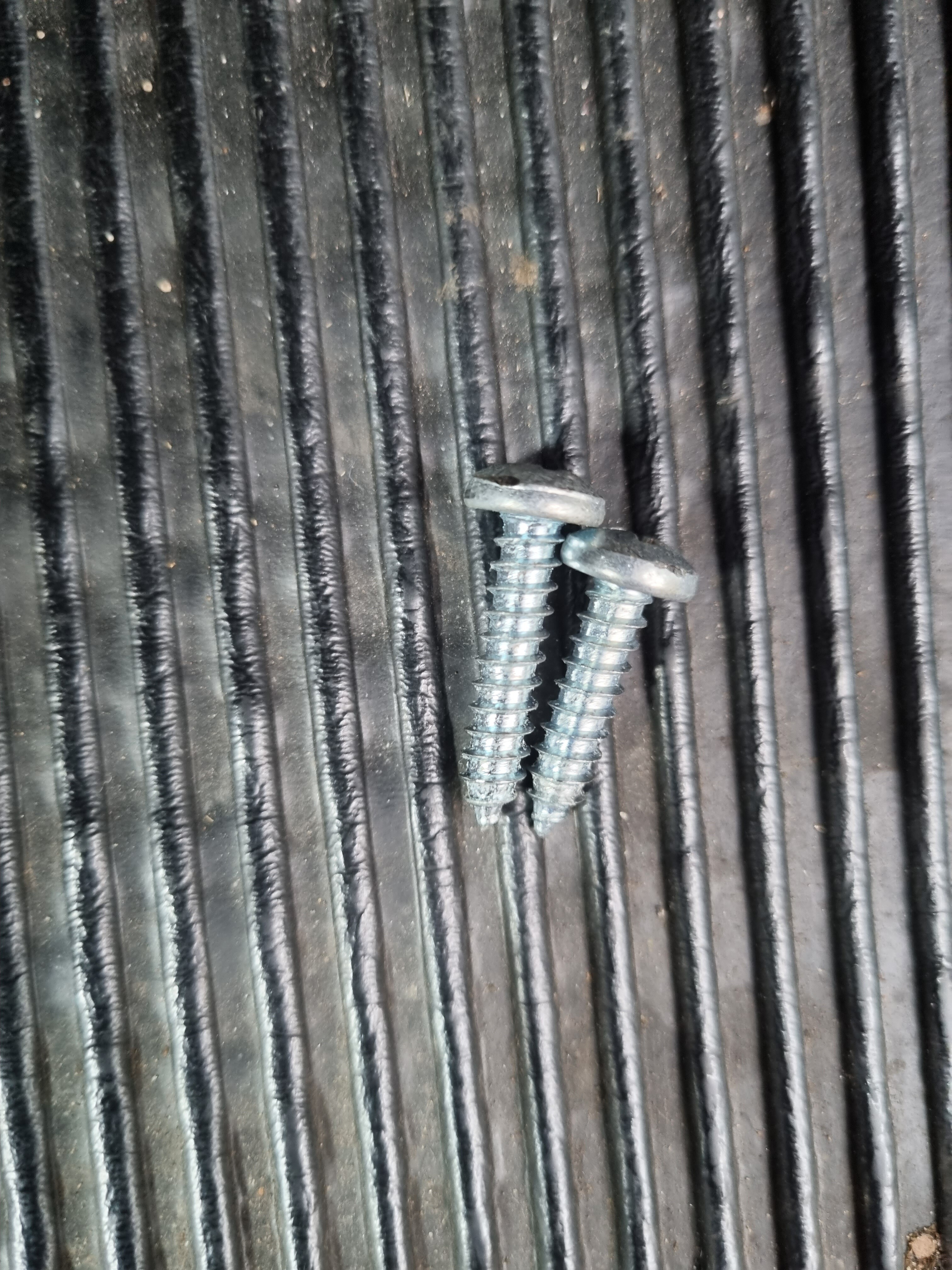
Remember to keep screws/ clipped grouped

2. Identify the wiring and colours
What you are trying to find is, what is listed on the installation instructions ( Included with Easy Guard )

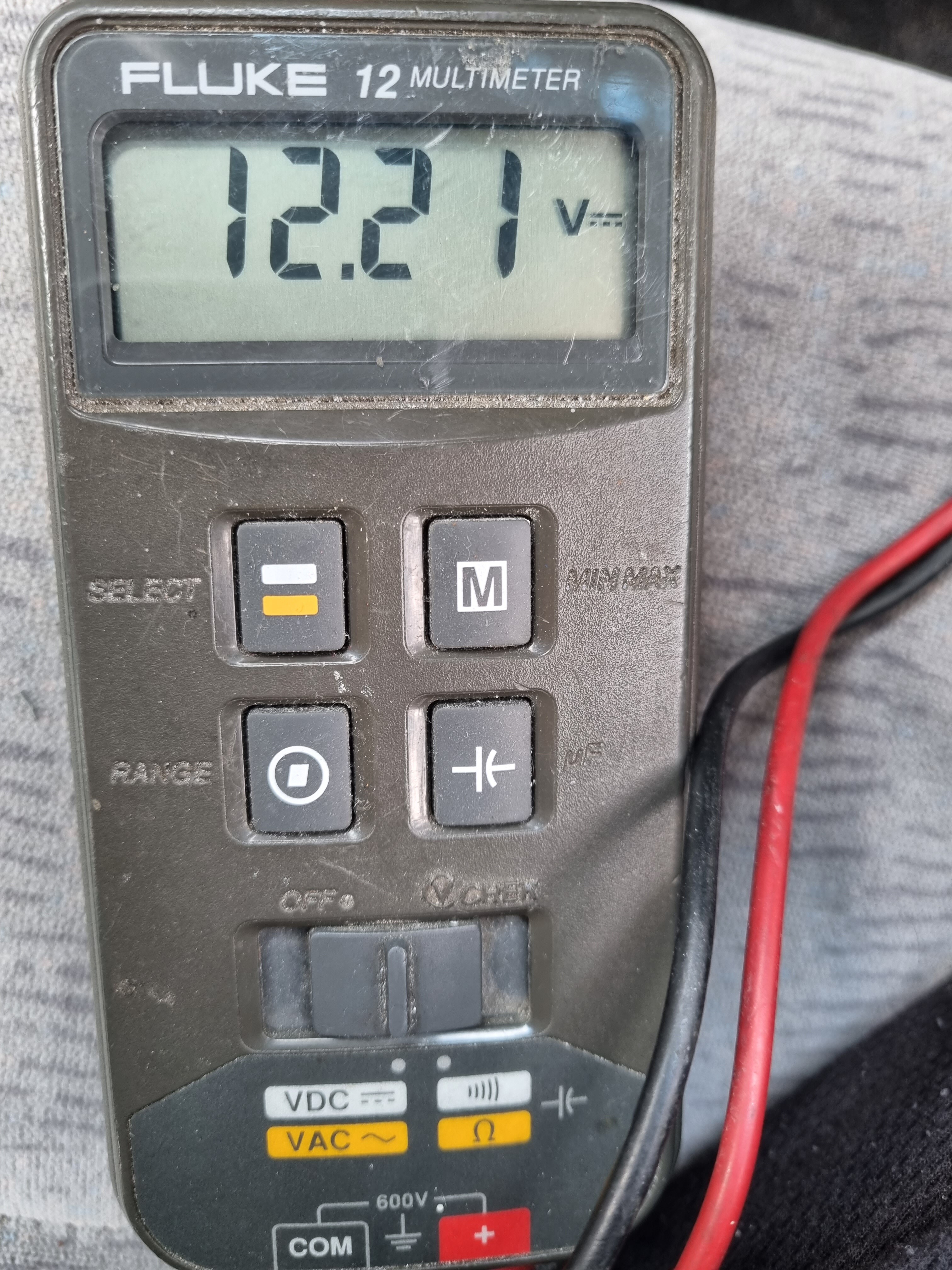
This means, when does each wire coming from the ignition have 12V on it.
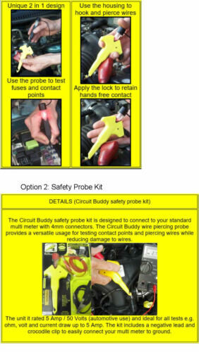
To do this, the easiest tool to use is a Multimeter or voltage tester, (I used a voltage tester like this)
Test each wire coming from the back of the ignition wiring with the key in each position in the cylinder


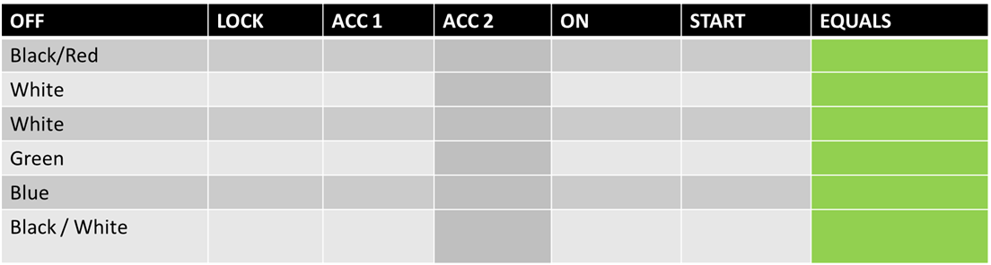
Here are my results , I have ticked when there was 12V on the wire
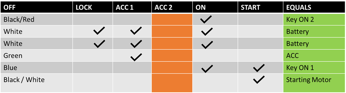
( I have put a blank template at the bottom of this post for your own use )
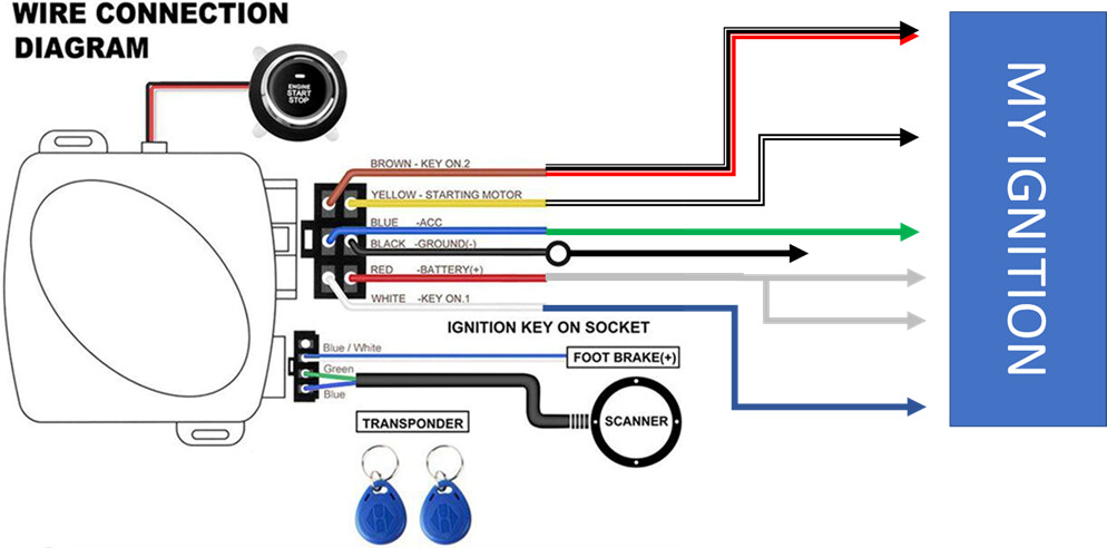
From this, we transpose the wiring to the Easy Guard Wiring colours
Here are my transpositions
( I have put a blank template at the bottom of this post for your own use )
3. Connect Wiring loom / harness
Now we know our wiring, we can
Disconnect the battery
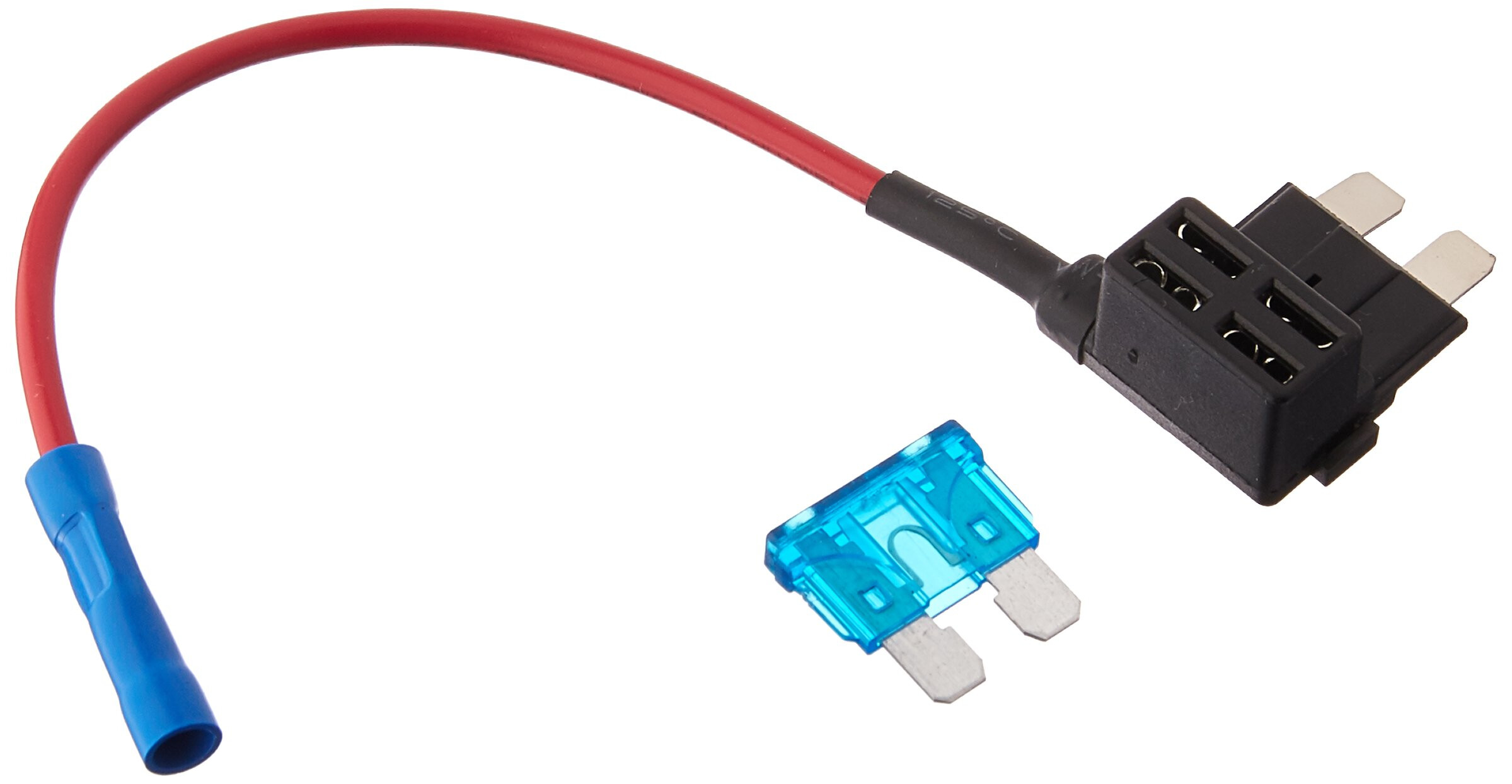
FUSE:
I chose not to add an additional fuse, as there is already one inline for the ignition system.
If you wanted to add one, a simple but effective option may be a Fuse Tap Piggy back
I like to find a chassis ground first,
Dont forget to carry out a continuity test with a multimeter before you commit (ask here or search Youtube if you are unsure how).
Luckily for me I found one, under the steering column, with exposed metal, a hole with an unused bolt going through it ( I couldn’t believe my luck )

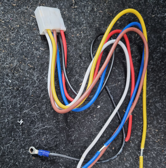
I just needed to add a ring terminal to the end of the black ground wire

Because this set up is made to be easily reversible, you do not need to cut any wires on your vehicle.
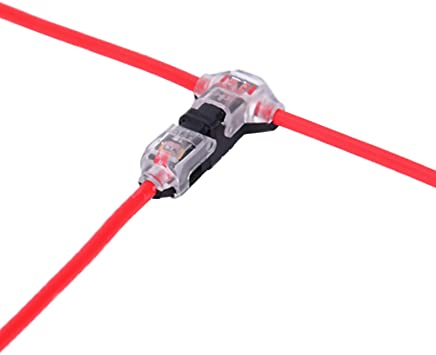
Personally I wouldn’t ( And didn’t ) use splice connectors
There are a few other ways to join these wire, Below is how I did it.
You can choose to do each of these one at a time, or all in one go…
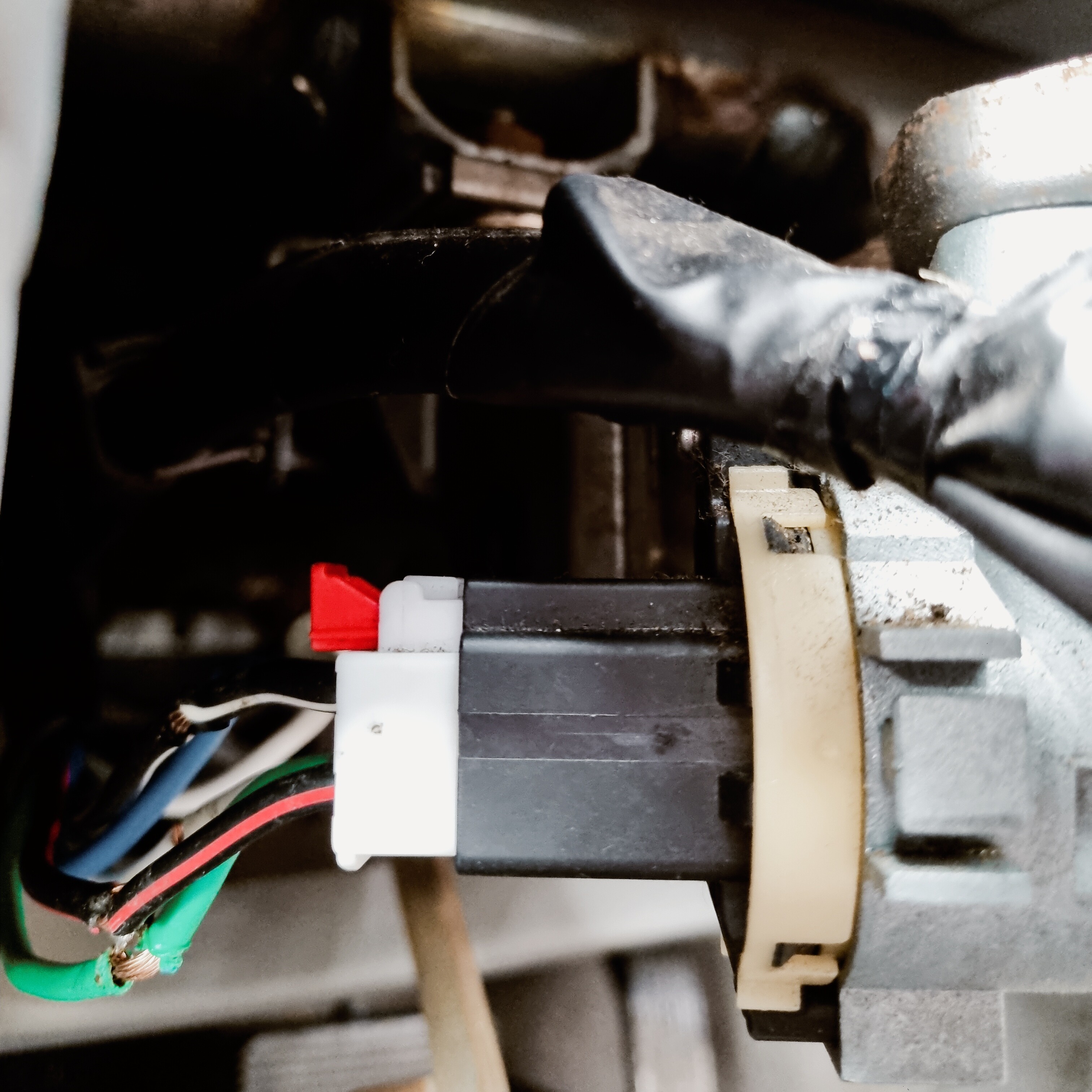
To make accessing the wiring, I unplugged the wiring from the rear of the ignition
On mine, the red tab is a secondary lock, This needs to be slid out, then the other tab pressed to release
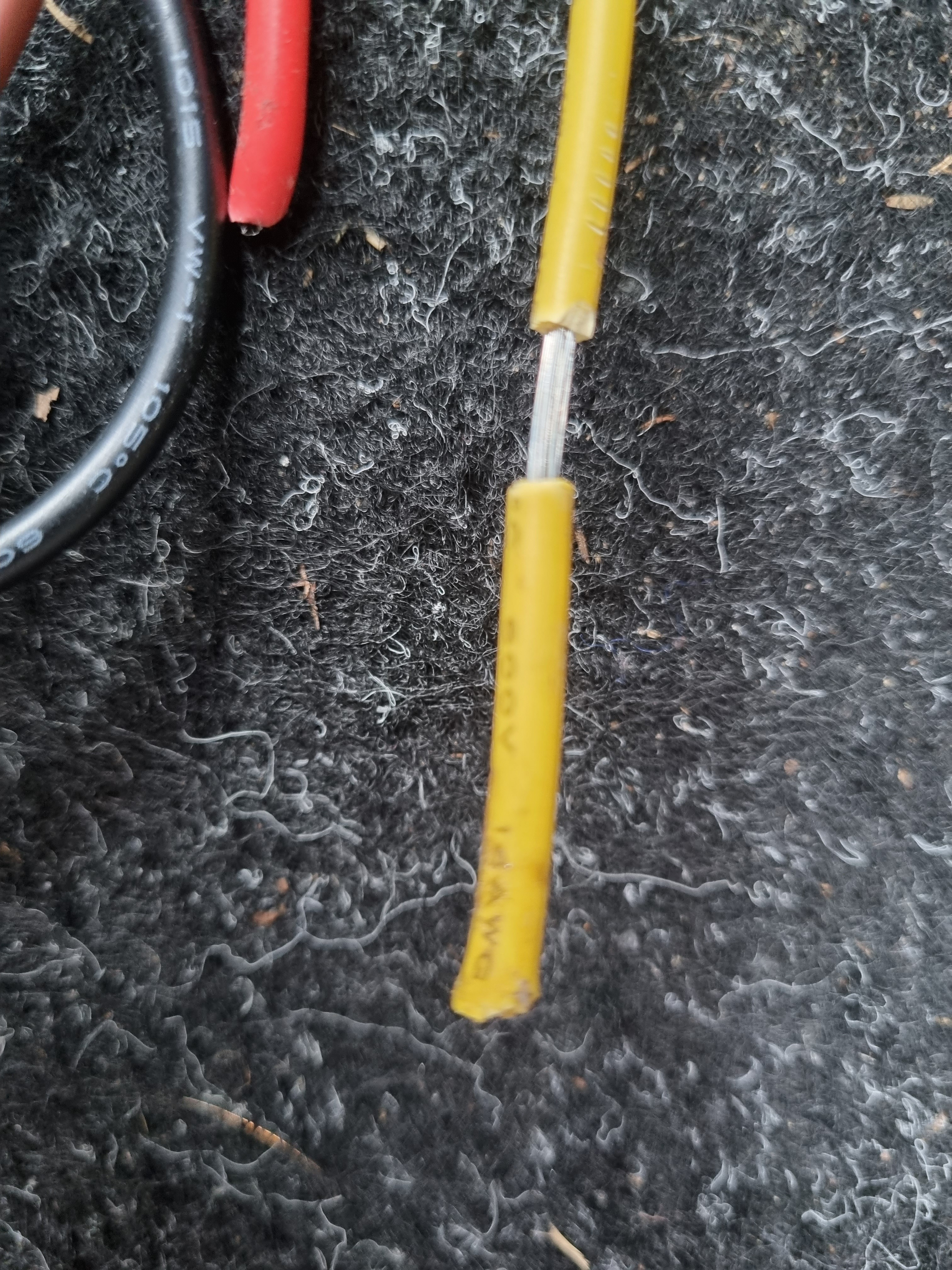
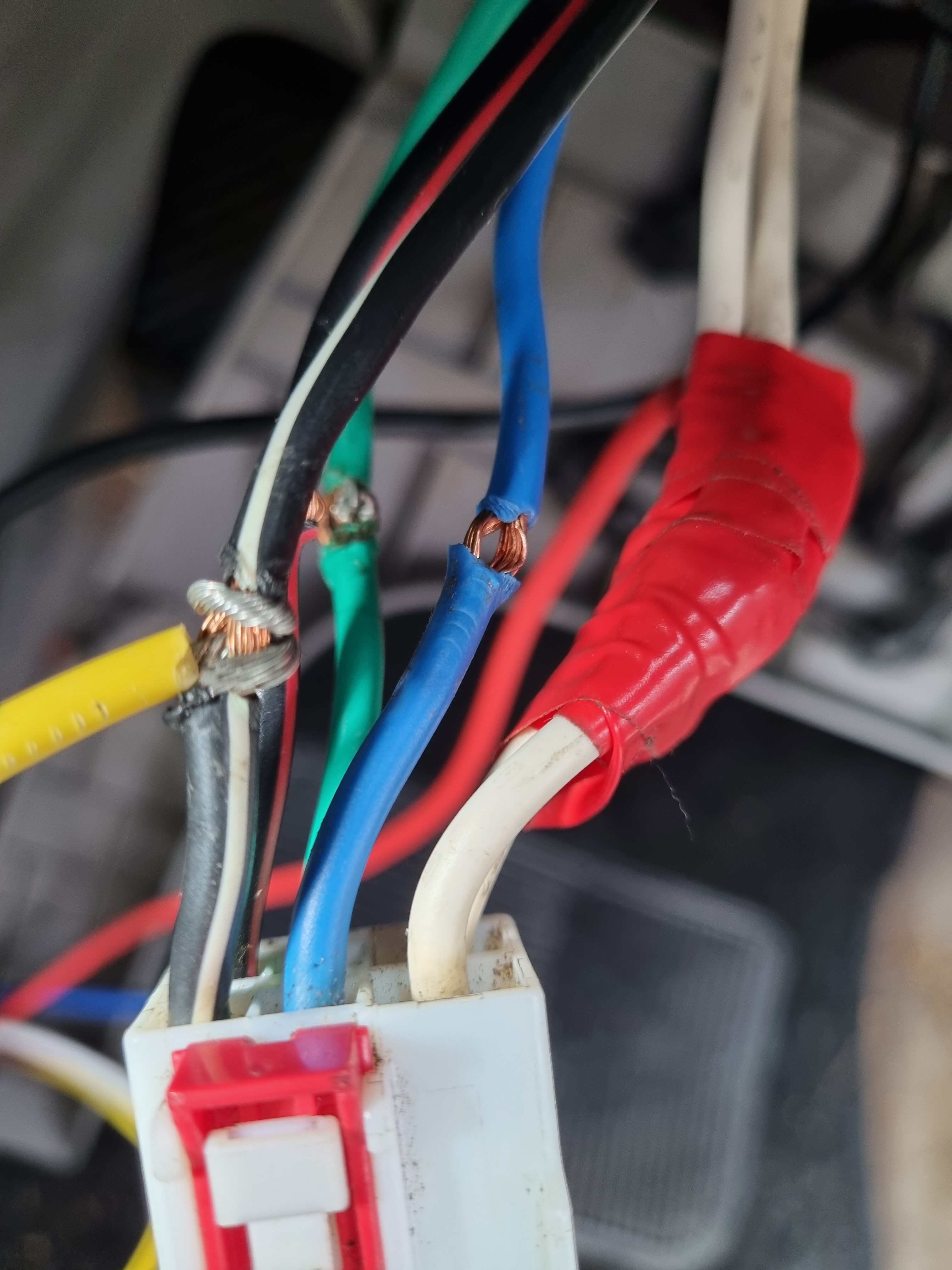
I used wire strippers to expose the copper strands coming from the ignition
then, I used a screwdriver to separate the strands to make a “tunnel”

I then stripped the end of the Easy guard Wiring Loom
I tend to strip a length long enough to wrap around the other wire at least twice
I also only just separate the sheath enough so when I am ready to expose the ends, I can twist and pull, thus making a tight wire with no exposed strands, which allows threading these though the Tunnels I made above, far easier
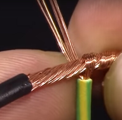
Also, as this ignition had 2 x 12V always on wires and the Easyguard only has a single 12V wire, I made a “T” or “Y” connection,

When the threaded wire is passed through, I twist the main wire, which tightens on the threaded wire, I then wrap in a method that is similar to a clove hitch ( wrap from one side to the other )

This provides a good electrical connection, but if you wanted to solder, now would be a good time to do so.
A “T” splice would also work well here
Carry out a continuity test with a multimeter (ask here or search YouTube if you are unsure how).
Now we need to insulate to keep you and the equipment safe.
Because It is not an end splice, unfortunately we cannot put heat shrink over the end, but a tightly wrapped and liberal amount of quality electrical tape will work perfectly adequately.
Do not pull and break the tape, Instead, use scissors to cut the length you need, when stretched the tape will slowly unravel and look messy and leave exposed sticky tape…pretty unprofessional looking
[Do not ask me if I used scissors ![]() ]
]


The Easy guard has a safety function, whereby the Brake pedal needs to be pressed before the vehicle can be started or stopped.

The brown wire isn’t needed, so it can have heat shrink or be taped on the end and tidied away.
The easy way to wire this for our purposes is, find a brake light wire and connect that to the wire that goes to the Easy Guard as shown shown above and below.
On this car, near the top of the brake pedal was a 2 wire automotive plug and socket.
So with a circuit tester or multimeter, we can find which wire has 12V when the brake pedal is pressed
Green in this example
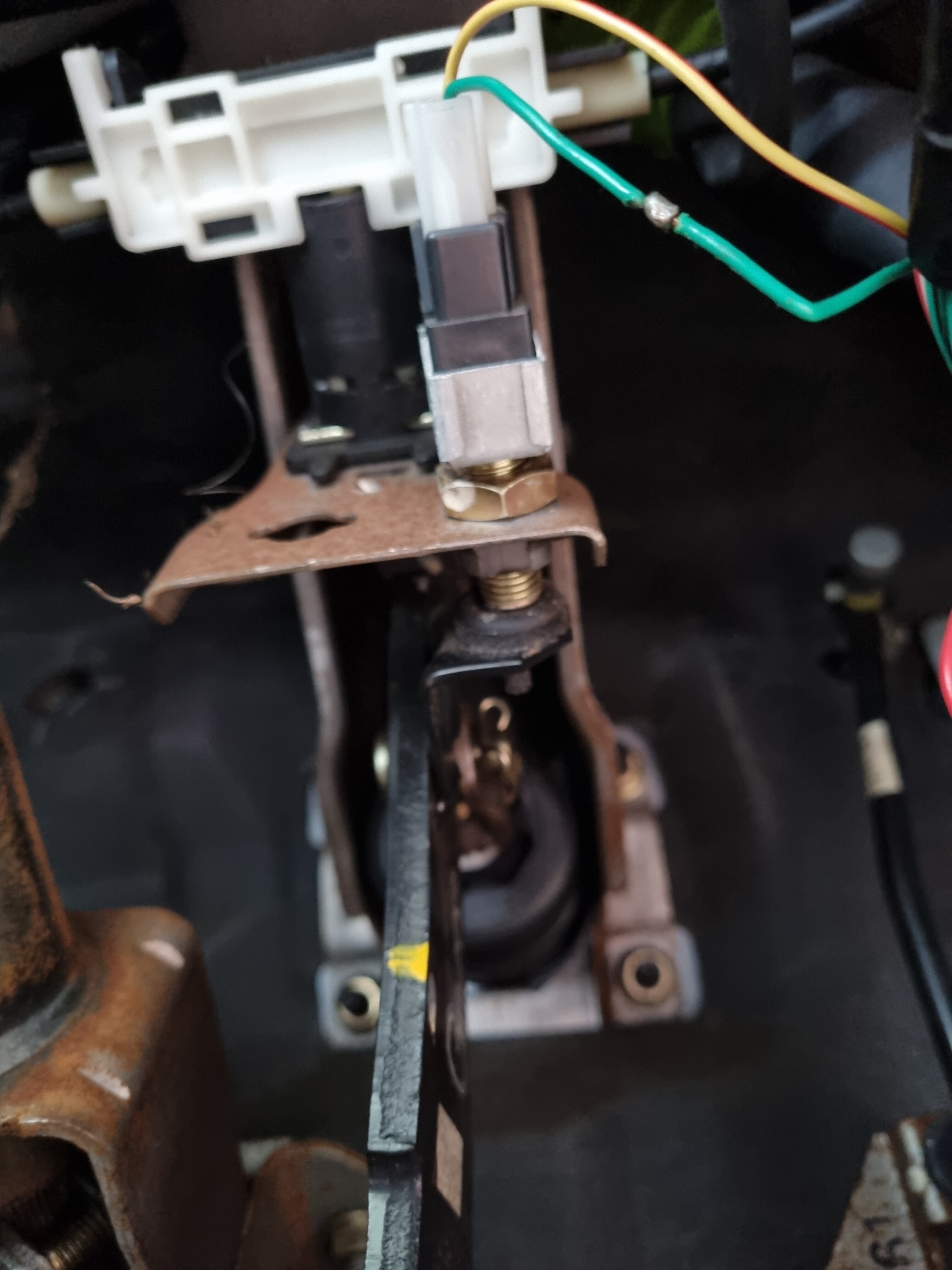
Because the wire is substantially lighter gauge, rather than going through, I just exposed the strands and I wrapped around it in a similar manor, and taped it to insulate.

Wiring done !!!
Writing this up has taken me longer than wiring it up
4. Time for the First test
Plug the looms into the Easy Guard Unit (Ignition loom, Brake safety, RFID antenna)
We need some power, SO Reconnect battery

OR ![]()
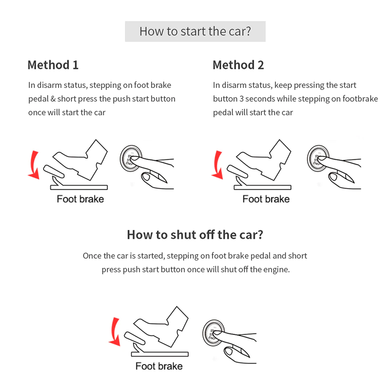
Abridged version:-
Push the Push to start Button - Nothing should happen
Swipe the included key fobs - two beeps ![]()
![]()
Push the Push to start Button without foot on brake - Accessories should turn on
Push the Push to start Button with foot on brake - Vehicle should start
Push the Push to start Button - Vehicle should continue to run
Push the Push to start Button with foot on brake - Vehicle should stop
Diagram Version:-
5. Final installation
You need to decide where and how you are going to do this for both the Easy Guard main unit, the RFID antenna and the Push to start button
You will be limited to the wiring loom length, unless you want to add an extension. ( Factory length is ~1 metre
For this install
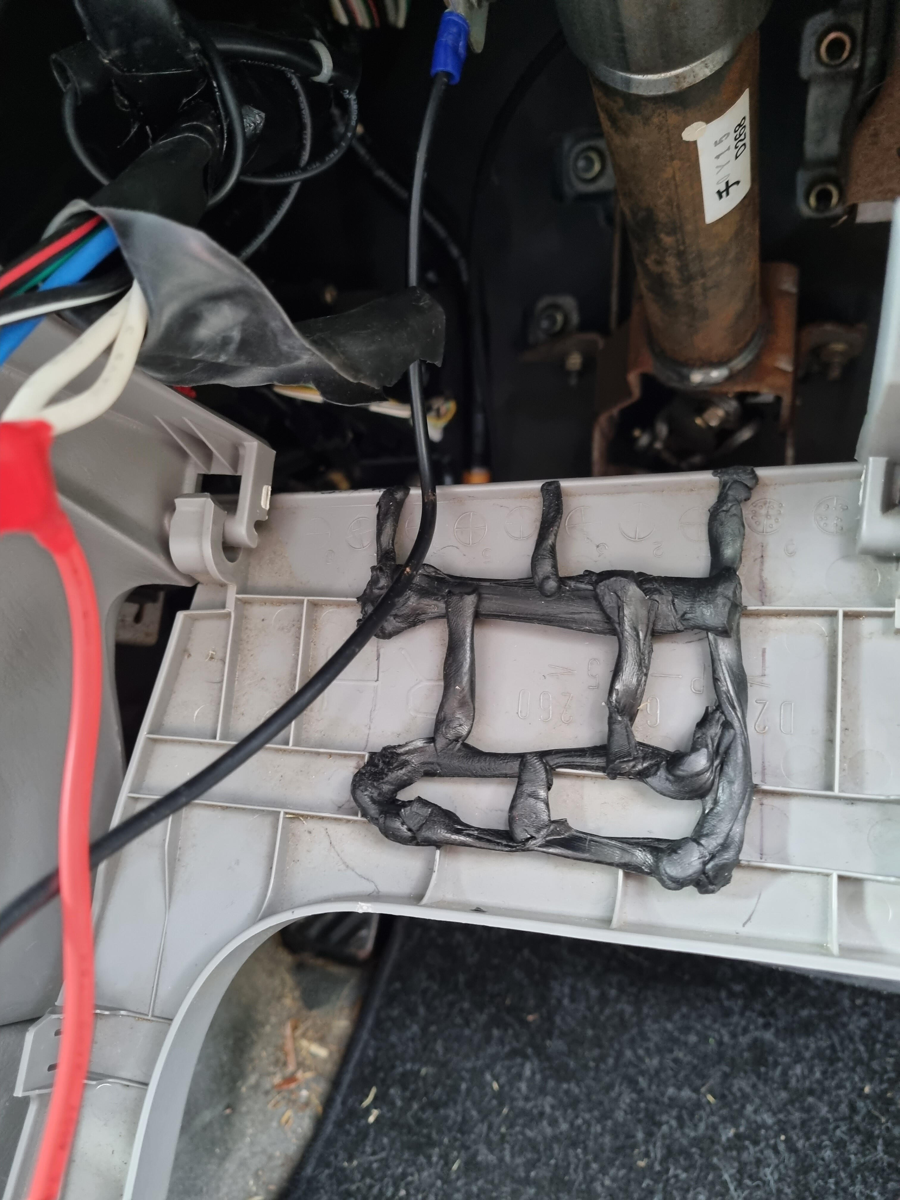
Main Unit
I chose a panel that is below the steering column
I attached with “Black Tack”( Like Blue Tack, but Much Much more tacky, and BLACK )

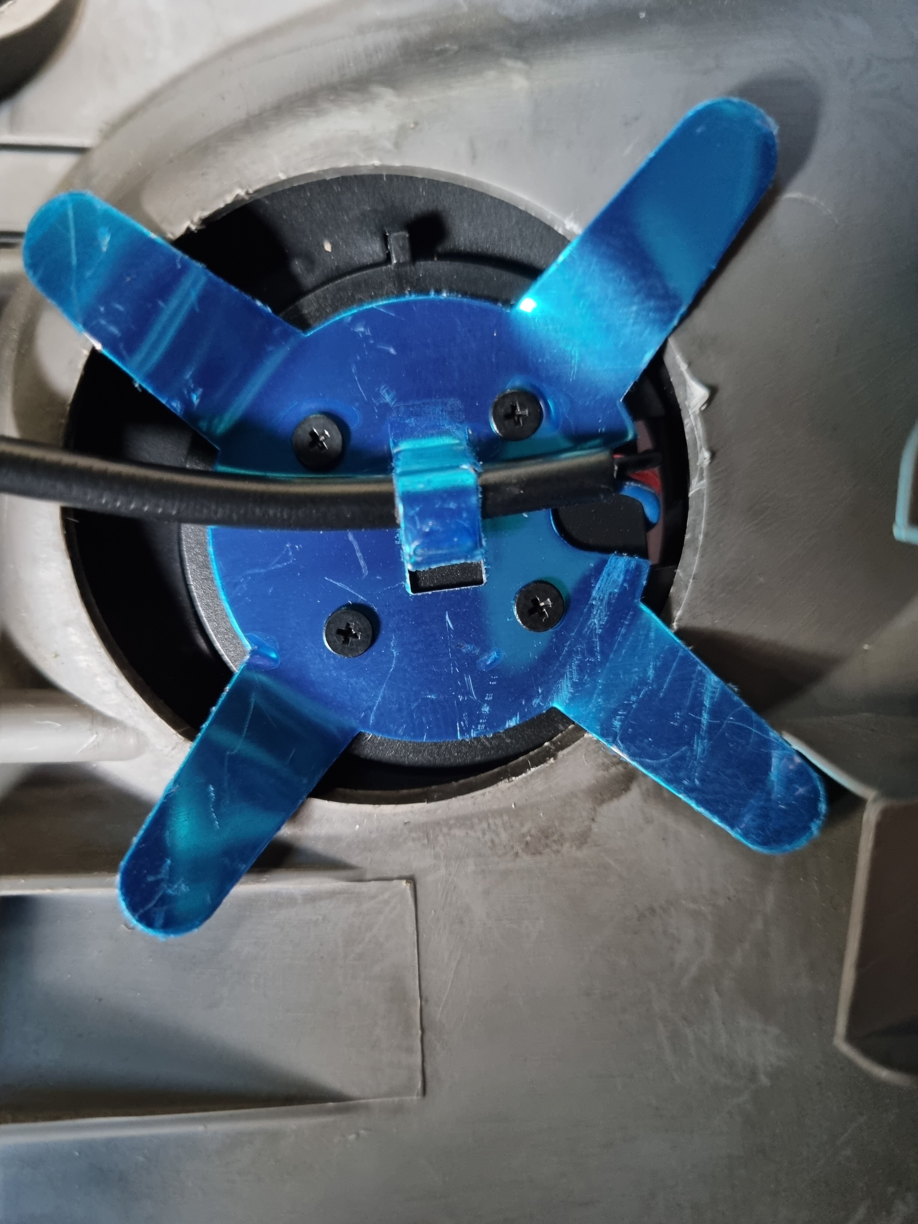
Antenna
The usable antenna locations I have identified CURRENTLY are:
Door Card
Windscreen /Windsheild
WIng mirror
Foot well panel
The choice will come down to personal preference and the implant / fob you are using
This particular install is for somebody without an implant, I have temporarily placed it in the coin/card pocket and it wedged in nice and snug

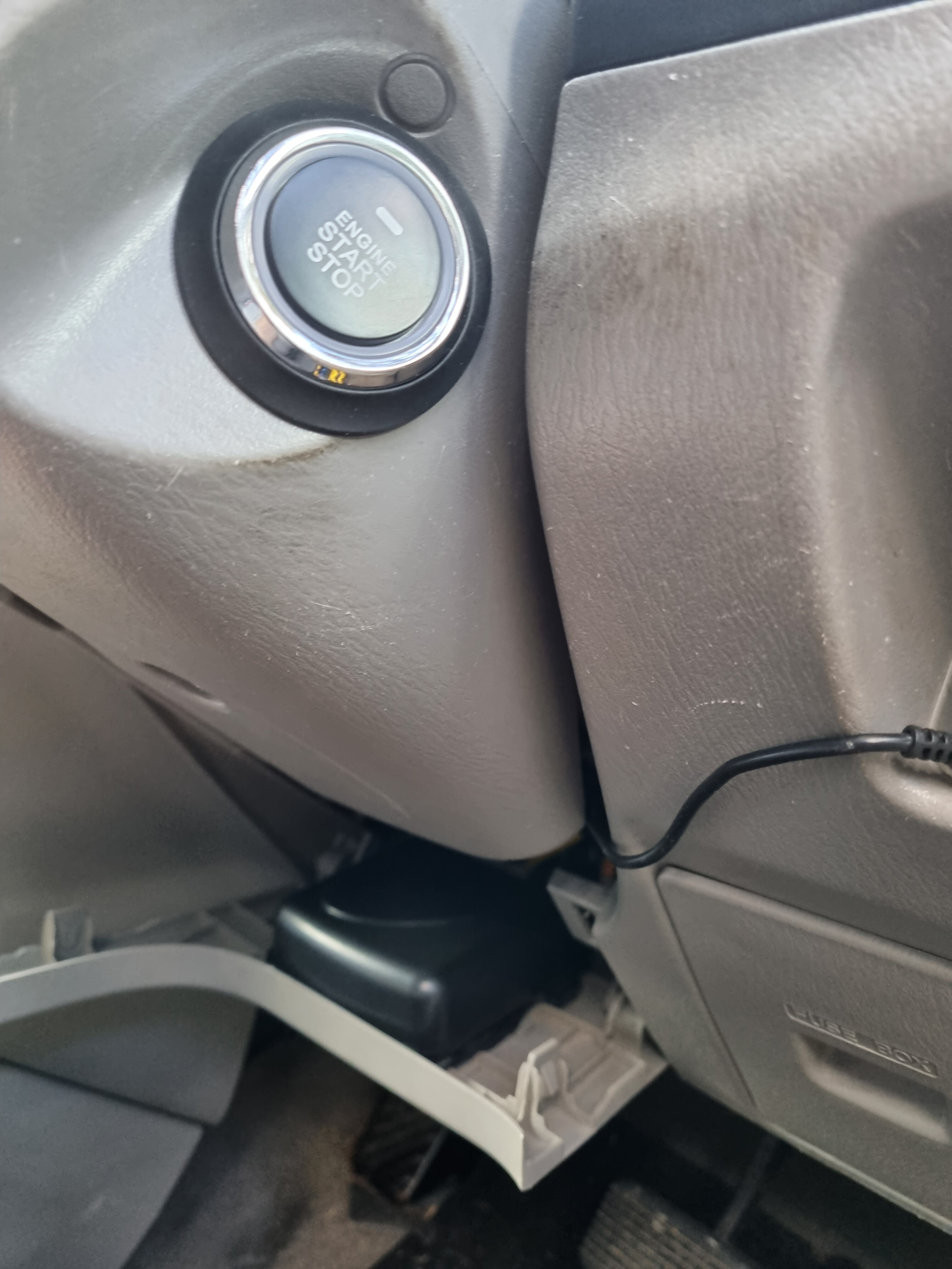
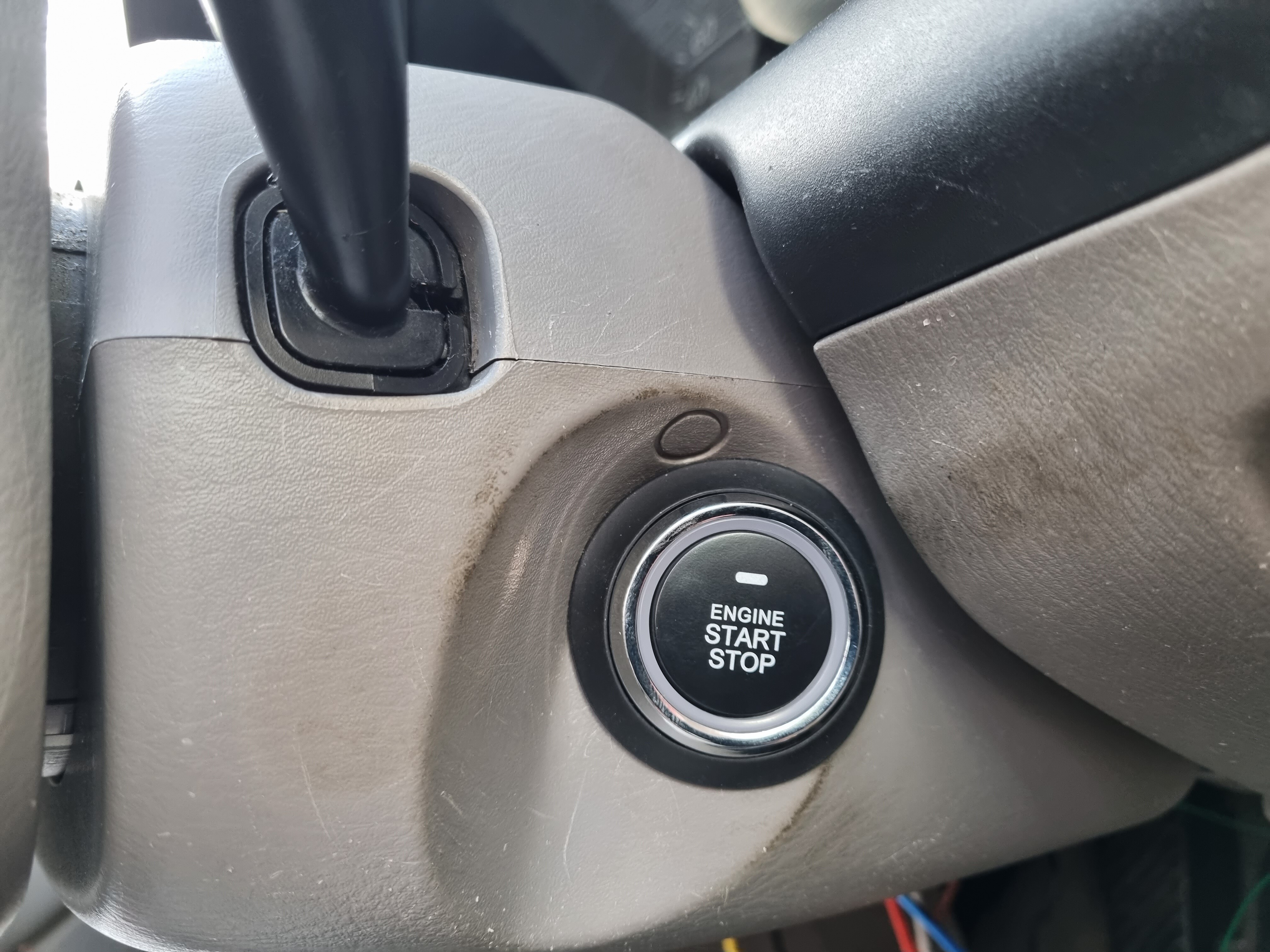
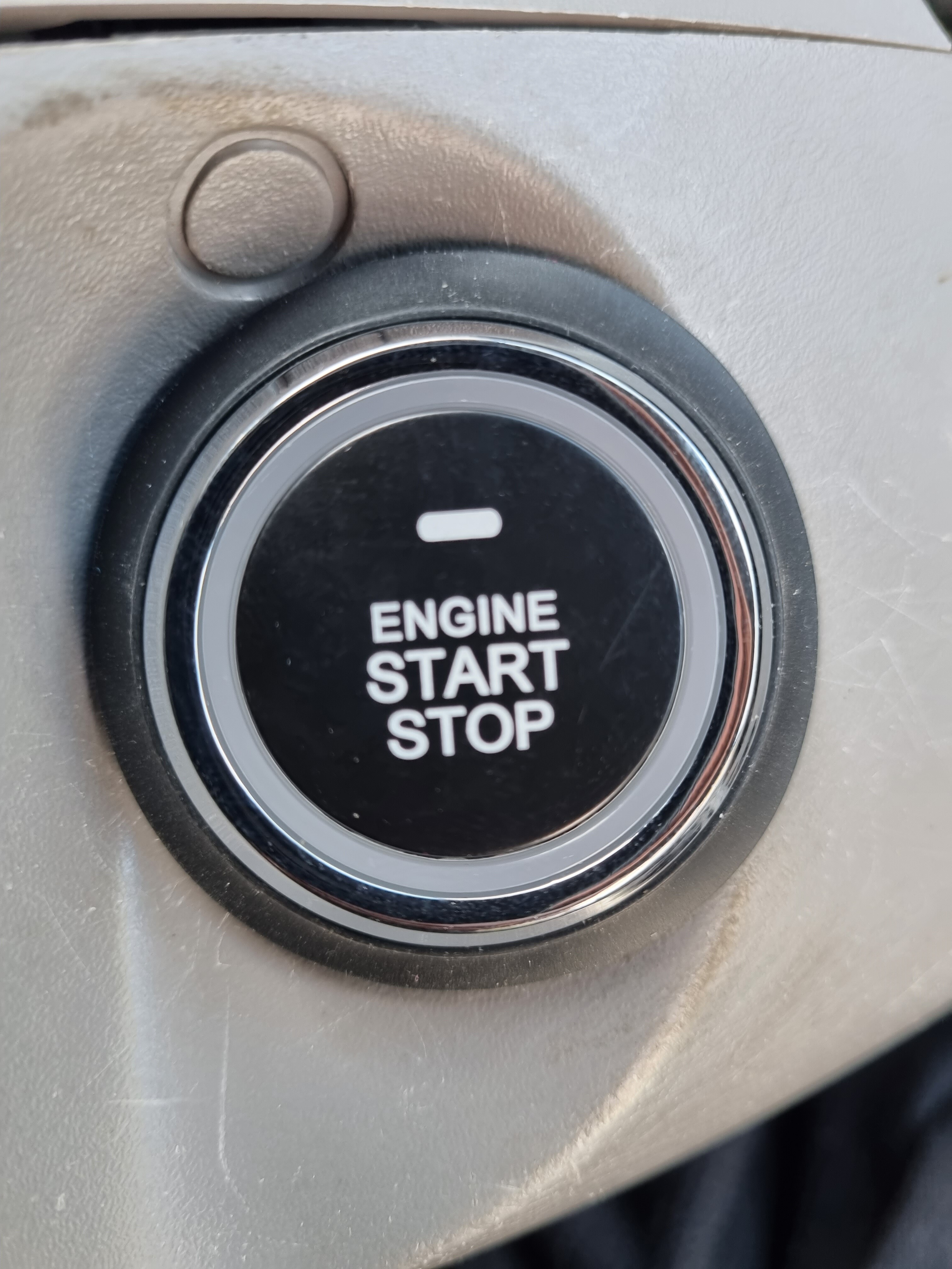
Push to Start button
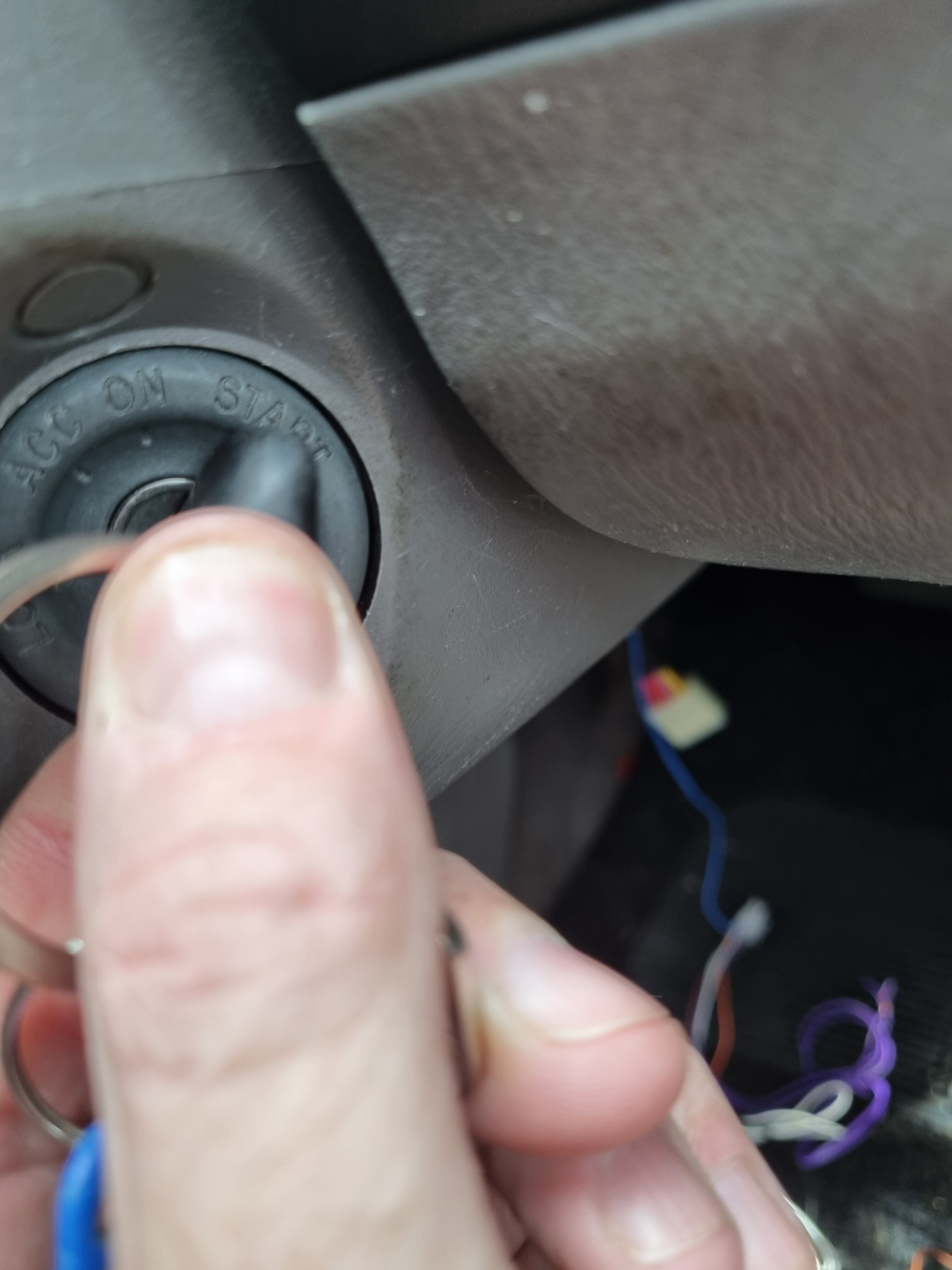
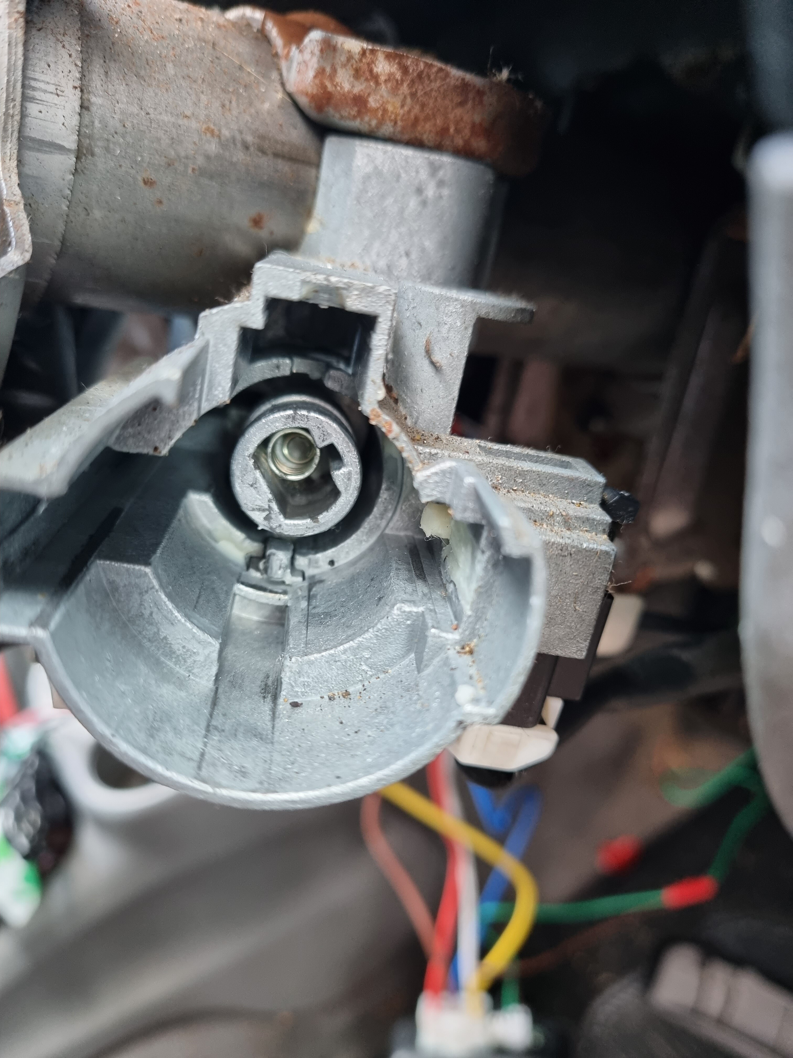
I chose to remove the key barrel, and place the Button in the hole, which fits perfectly
# Safety warning
To do this, you will need to leave the Vehicle without steering lock, again this may void your insurance, so make an educated decision.
To remove the key barrel, there should be a small “button” that you will press when the key is turned from the Lock position to the ACC position.


The barrel should slide out. (The steering is now unlocked)
On the shroud I removed earlier, I installed the Push to Start Button, I reinstalled the shroud and ran the cable back to the Easy Guard Main unit, ensuring to keep the wiring clear of chafe points and Cable tied ( Zip Tied ) and taped the cables to fixtures, again to prevent chaffing.
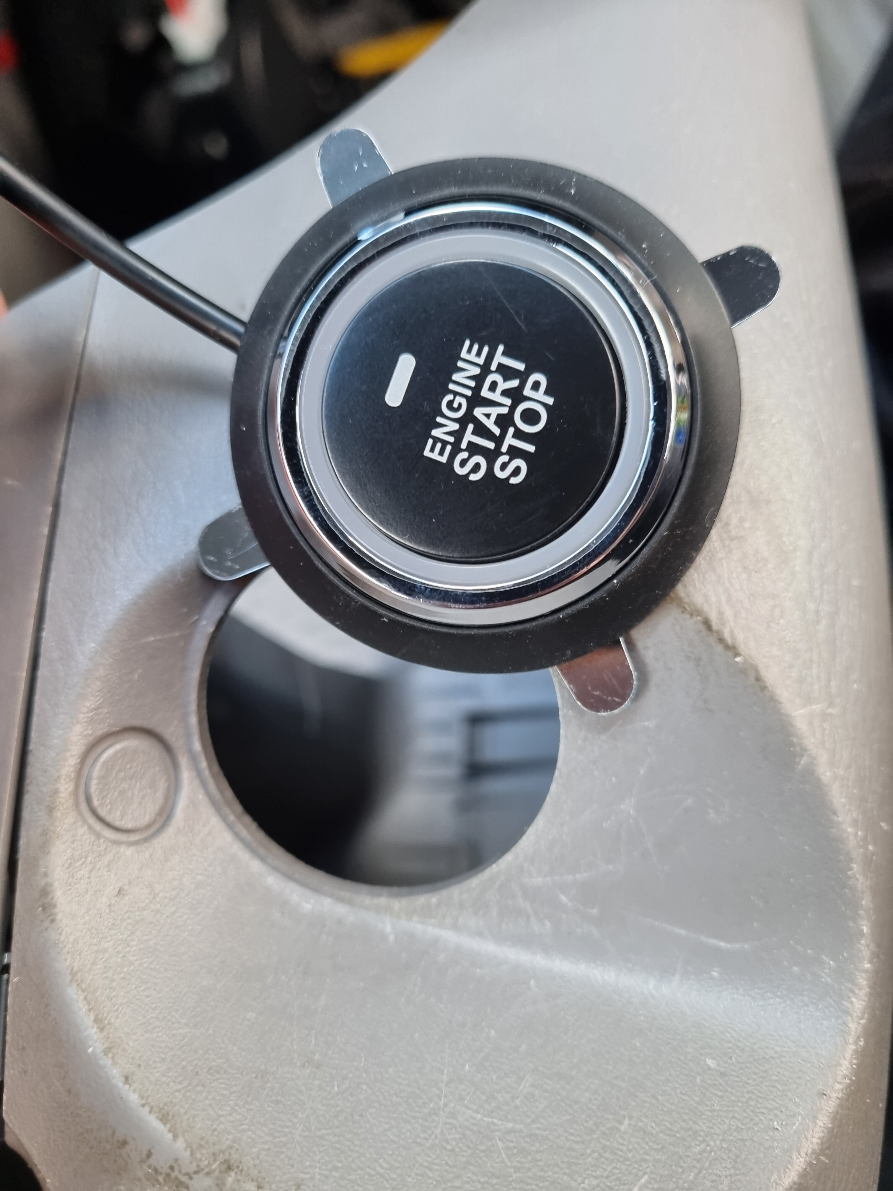
FINISHED
- Extras / Q&As
Q. What sort of range can I expect from my implants
Range tests ( Bench Test )
A.
FlexEM
NExT Implant
As you can see, and would expect, the FlexEm out performs the NExT, ITS PHYSICS BABY so you may need to place your antenna accordingly.
Q. My car has a transponder chip, can I still use this system
A. Yes, but, you will have to:
a) Remove the “transpodner chip” and place it in close proximity to the antenna ( Likely around the ignition barrel )
b) put a spare key ( or just the chip ) into a “Transponder bypass” like shown below.
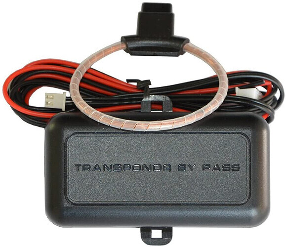
Transponder Bypass link
Be aware, if you bypass your Transponder system, this MAY invalidate your insurance
Q. What if I want to use a key as a back up
A. If you put the push to start in an alternative location and leave the ignition in situ, you could use either key / implant / fob to start the car,
I have not tested the circuit and therefore I am un aware if there is any circuit protection so a diode may be required to protect. ( They do claim it, but I don’t known whether to trust it )
Q. Quiescent current
A. ≤25mA Quoted, Not tested
Q. Should I bench test before I install
A. Absolutely, all you will need is a 12V power supply / battery, Don’t forget to including enroll your implant
Q. Can I unlock my doors with this?
A. Well, Kinda, I have a solution, but it is not as polished as I would like, so I won’t be adding it to this install or providing it here.
But watch this space…
Separately, there are some “Easy Guard” systems with Door Lock / unlock included, BUT it doesn’t work how you would expect, I have one of these and If I get some I will have a look at this to see if I can adapt it.

Templates

TBC
I hope this helps somebody, any questions just ask
-