Also what i forgot to mention to putting multiple in paralell: the more you put in paralell the beefier your gate driver has to be and at 7 MHz it already has to handle more than 8A peak just charging and discharging the 300-400 pf of the Gate. I don’t know what driver ic you are using and what peak current it can handle but it might already be at its maximum capacity with one mosfet.
https://www.mouser.com/datasheet/2/698/REN_isl55110_11_DST_20061211-1529113.pdf
It has 2 outputs that are tied together in my design and that combined with:
The high peak current capability of the ISL55110 and ISL55111 enables it to drive a
330pF load to 12V with a rise time of <3.0ns
~73ms between peeks would be 13.56MHz so seems like it should have plenty of headroom.
I can’t quite recall how sine like it was, was somewhere between a square and sine but definitely sine leaning. @Satur9 might be able to grab a photo.
1 Like
I love it! Hell yeah, very cool progress in this thread.
Are there any updates on the bracelet? My blinkies are dying to be used.
there are a few people doing different things with this, but people are also very busy with day jobs and other life things. if you can offer some help or expertise, feel free to jump in and help out~ it’s an open community project ![]()
2 Likes
Yeah sorry for that. I’ve been very busy and haven’t had time to continue on that project. Saturn sent me some more test xled’s and a lovely test card with power harvesting chip but i’ve been so busy that i didn’t even manage to continue my other projects. This might change soon though since a 2 week holiday is starting to come up for me starting next week. I can’t promise anything though
1 Like
Take your time, don’t forget to enjoy your holiday.
1 Like
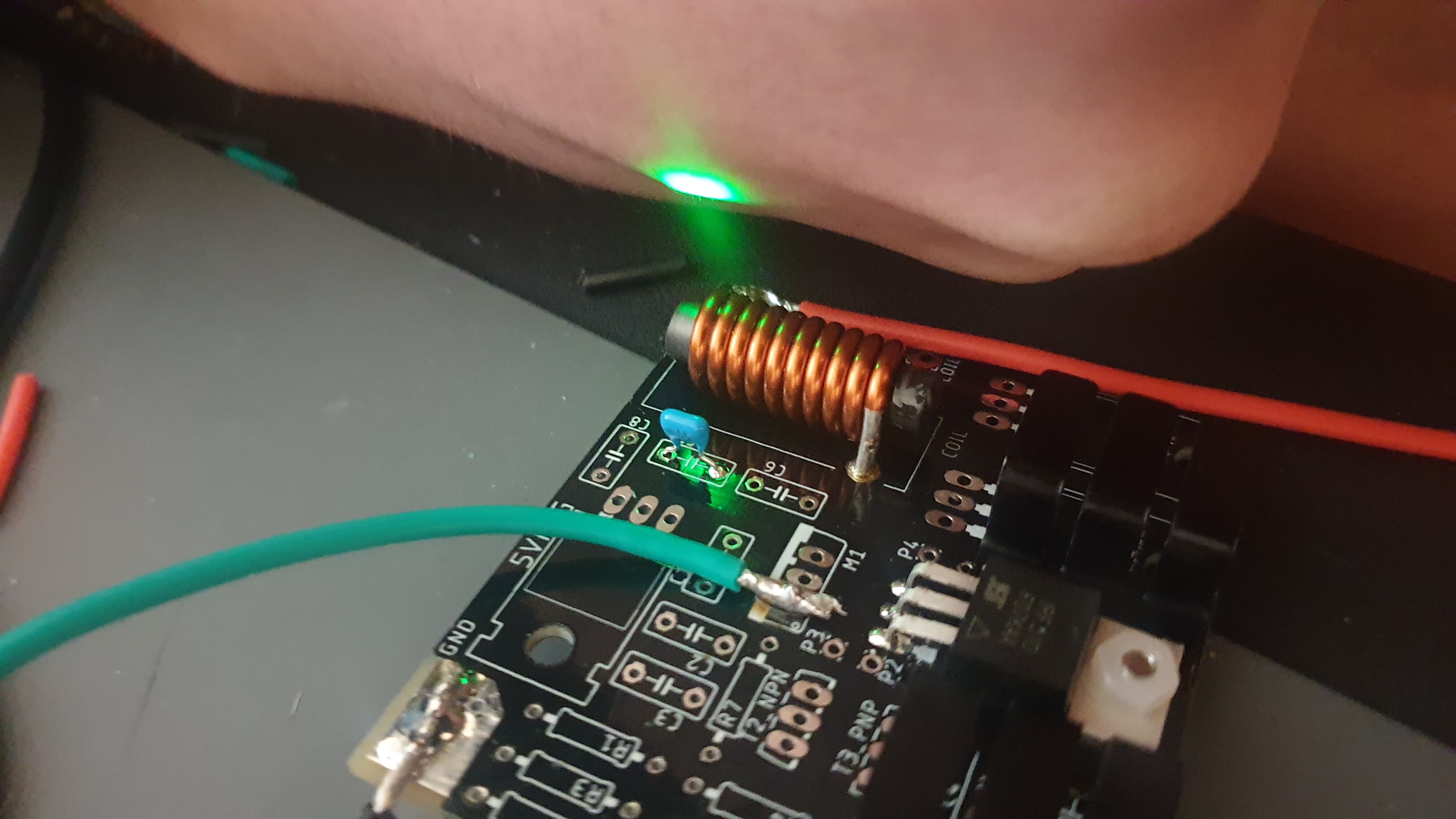
Not a big update but an update non the less… i now got an LC meter which enables me to accurately measure the inductance of coils and capacitors even if they have a small value. I also found out a method to measure/ calculate it otherwise.
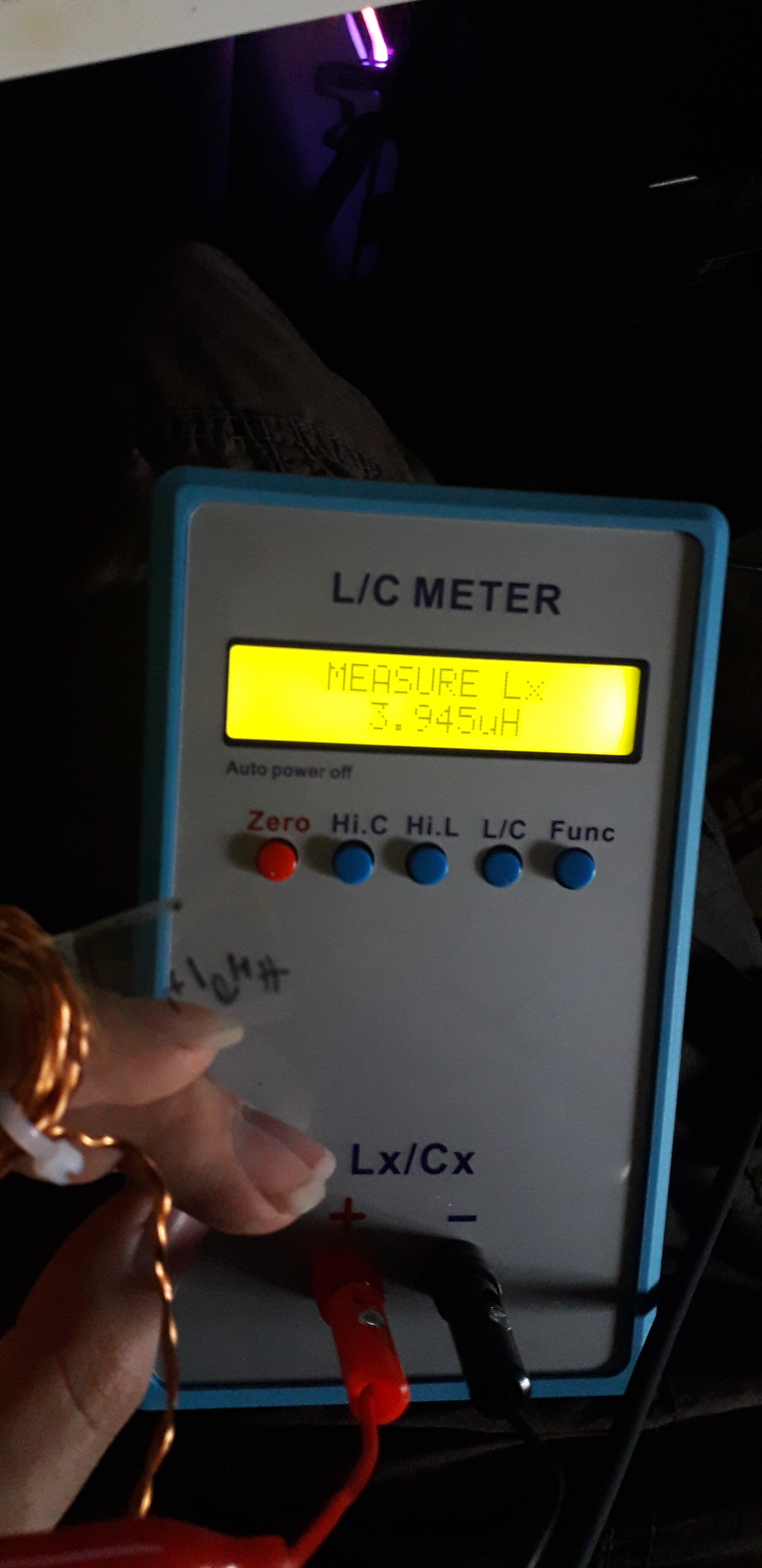
This was a test to see if my calculation was correct since i wound that coil when i didn’t have the LC meter yet.
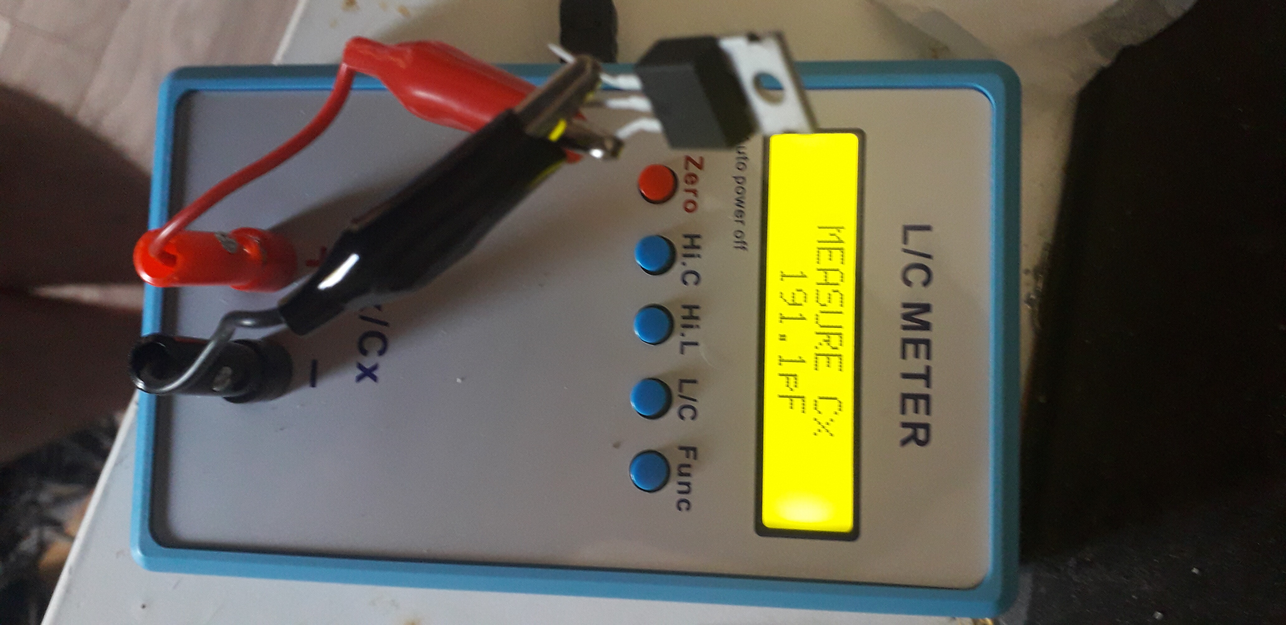
It’s also pretty usefull to measure gate capacity of mosfets. This is an original irf510 purchased from mouser. Right in spec.
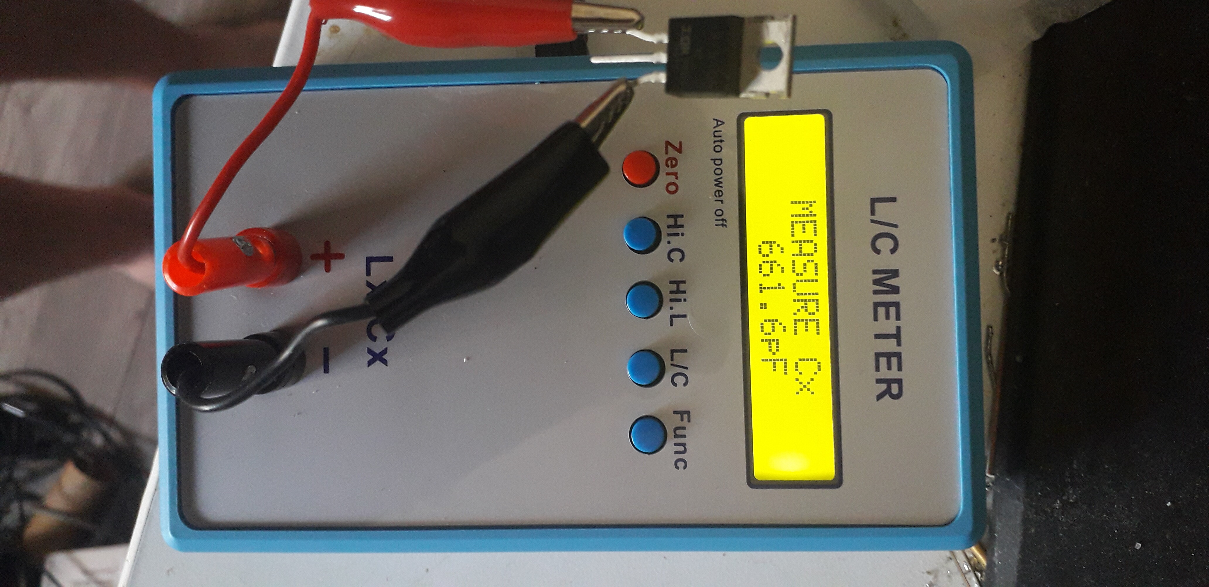
This one on the other hand came from ebay and is a fake. Probably a relabel of a different mosfet. Probably a irf520 or irf530. They will also reach high frequencys but their gate capacity is 3 times higher which means they take 3 times more driving power than the original at the same frequency. Also the miller capacity is way higher which further makes it hard to drive them at high frequencies.
Thats it for now
4 Likes
I’m not sure if this is the right place to ask this, (if not please direct me)
how far are we able to pushe the 5 volts from the transmitter for an LED implant. I realize it is most likely different depending on it being 13.56mhz or 125khz. but are we able to push from a wristwatch location to the webbing yet, about 10-15 cm? (@ either frequency)
I don’t think from an electrical standpoint that would be a problem. There would be a lot of issues getting that installed and, even if you could, it would take a lot of wear and tear with all of the bending your wrist does.
I was thinking like a bracelet to be worn outside your skin, that runs on batteries and transmits power 10-15 cm to the xLED style implant. my thoughts are, if you’re going to put LEDs in your body, you would want them to light up more often than just when your phone is 1 cm away trying to get it to light. I would anyway.
Oh! Yeah, that’s doable. If you check out the xLED page you’ll see a reader with a ring antenna lighting them up.
It’s the current brainchild of a few here on the forum!
1 Like
A few people on the forum were working on a similar idea not too long ago, you might want to check out this thread
4 Likes
@RaptorJeebus has some parts on the way and is going to make an instructable style DIY guide for soldering together a keychain version of the Power Accessories project on a proto/perfboard
2 Likes
That is the plan, But might be going a lil slow due to current shipping delays, Chip shortages, Plus I might be covid positive right now, But it shall be worked on!
1 Like

1 Like
Thankies! I got tested yesterday so I should have the results within a couple days, Fingers crossed! I can do some design work in the meantime!
2 Likes
Of which circuit might I ask? The mosfet driver / crystal driver chip based one, or the pierce oscillator one?