So this came up in another thread, and I know there are plenty of instructions on the net to do this, but I thought maybe someone might be interested to see what I was talking about, and how I do it. So here GOES.
First, the disclaimer. Electricity hurts if misapplied. The rest should be stunningly obvious. I make sure I unplug before working on it, and stay away from the capacitors. Any decent design should self-discharge, but things happen. I’m just sayin.
There are adapters that plug into the connector (ebay / amazon) that accomplish the same thing. But there’s alot of value to learning it yourself. Also, it leaves the wire tangle mess intact. However, if you’re not up to this, that’s probably your best route.
A basic power supply can be pulled from almost any desktop PC. Got an old pc running XP sitting in the closet? Great you’ve got a victim, er donor.
Step one. Check the label. They should all have one. It will let you know exactly how much it’s capable of supplying. Pay particular attention to the 12v, 5v, and 3.3v as these are what we will be concentrating on. They’re also the most commonly used voltages.
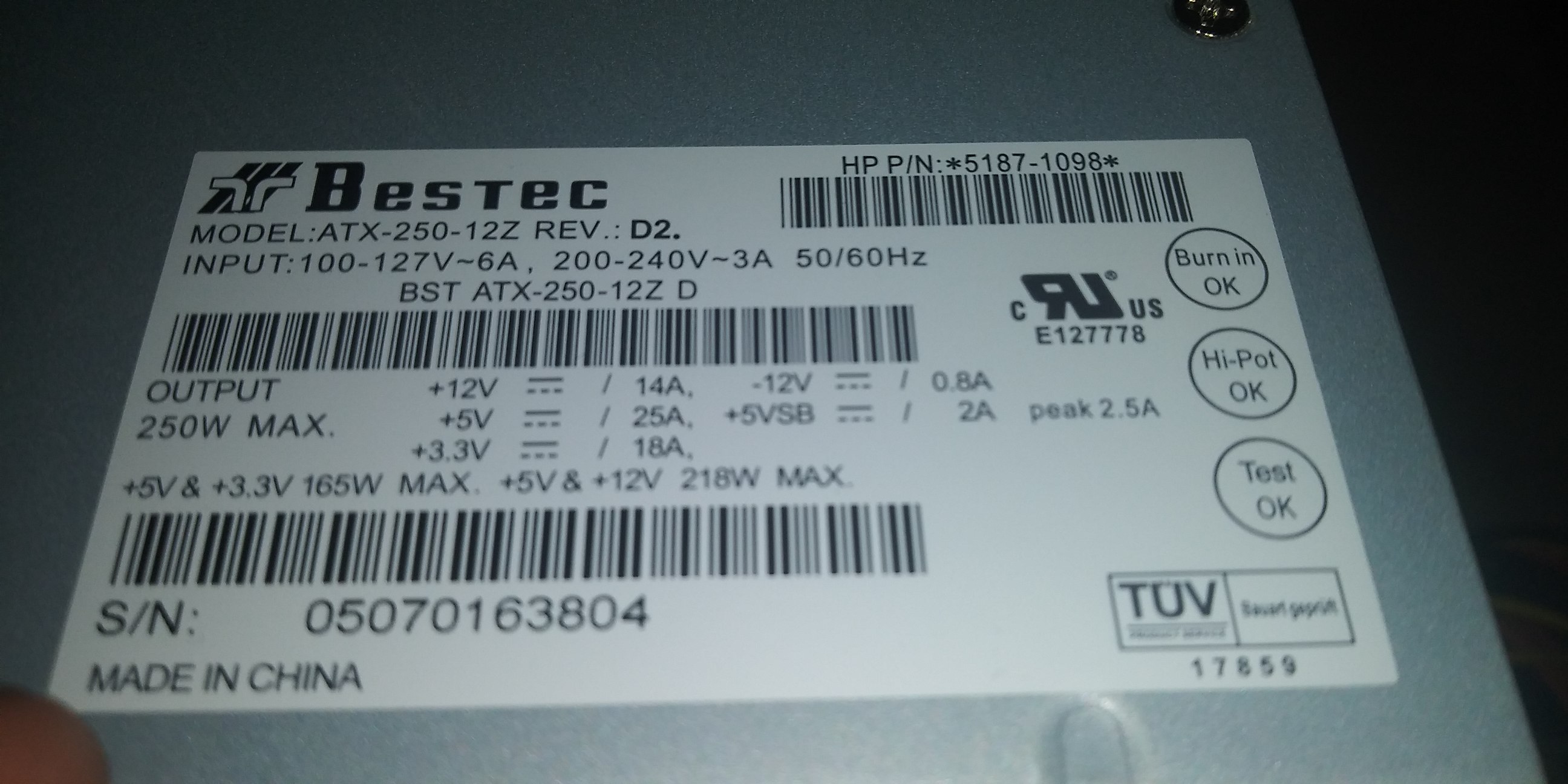
Optional info. Some P/S’s will have an on/off switch (I like those) and/ or a power LED (meh.) If you don’t have, they can be added. More later.
Step two. Before we go too far, I wanna know if it’s any good. The simple way to do that is to plug it in and turn it on. Plug is easy, but the internal wiring is set up to come on when the green wire (there’s only one) is connected to a ground wire. (black, lots of 'em) Connecting a jumper across the two at the connector should cause it to power up. Fan will probably come on, and you can check for voltage via multimeter. The important colors are 12v Yellow, 5v Red, 3.3v Orange, and Ground is Black.
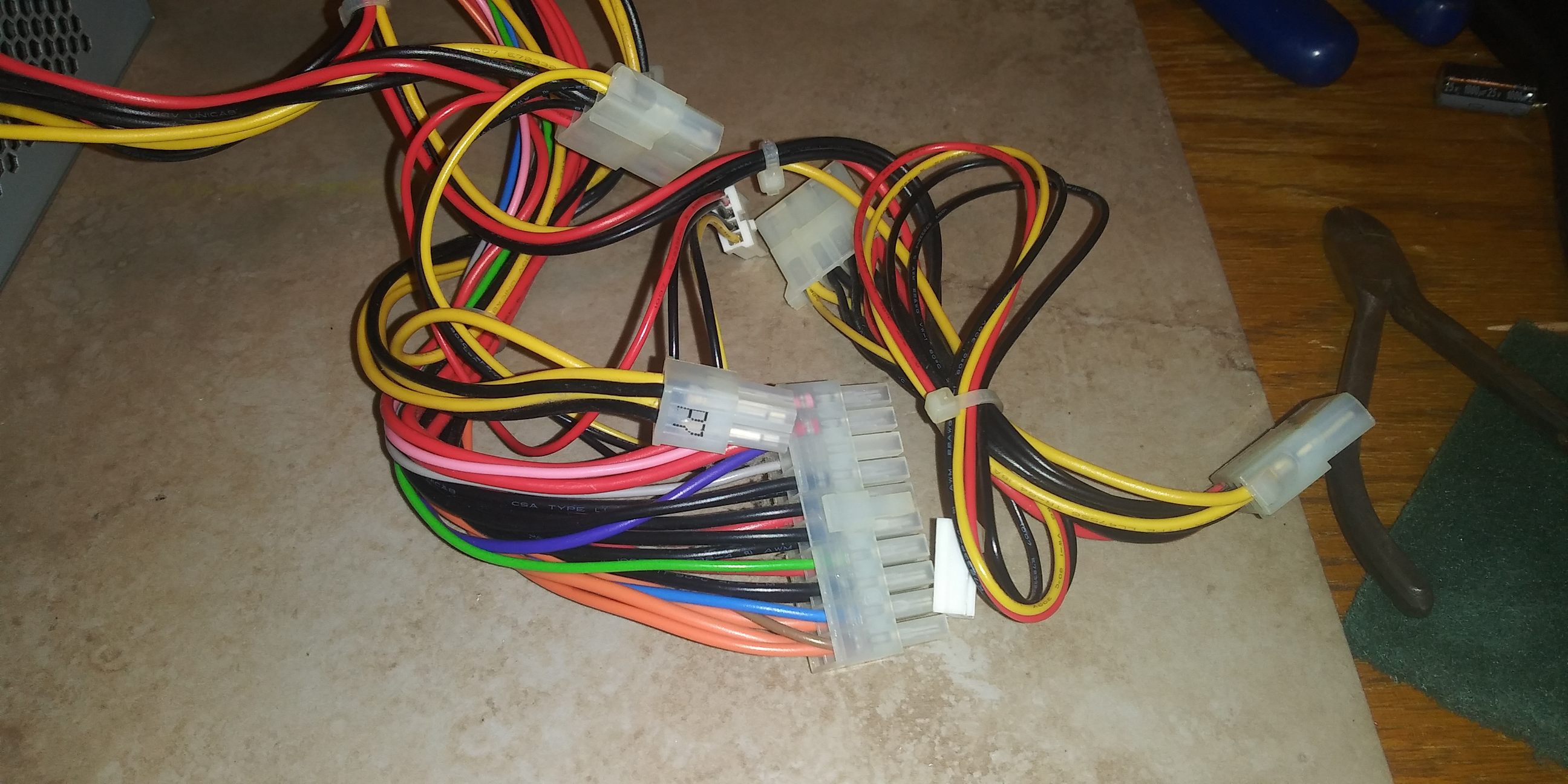
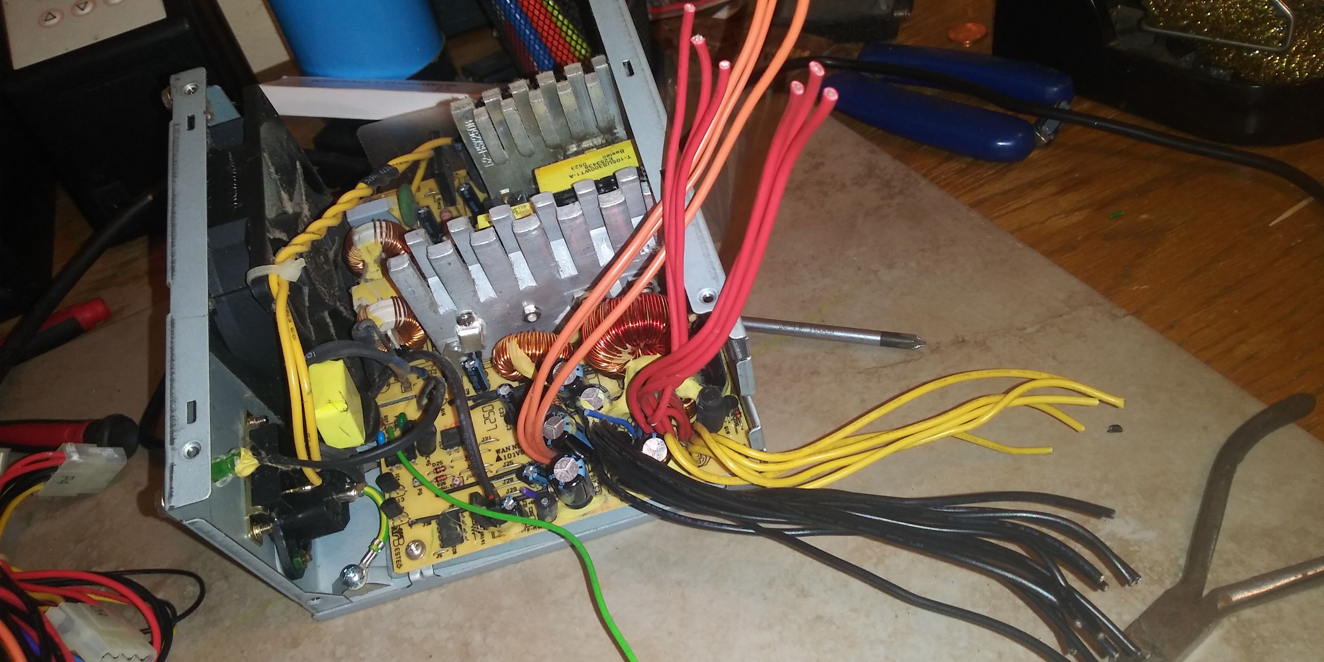
O.K, now that I know it’s viable. UNPLUG. and then pop the cover off. It’s a handfull of screw and the edges of the metal tend to be sharp. All the wires are now visible. Let’s start whacking them off.

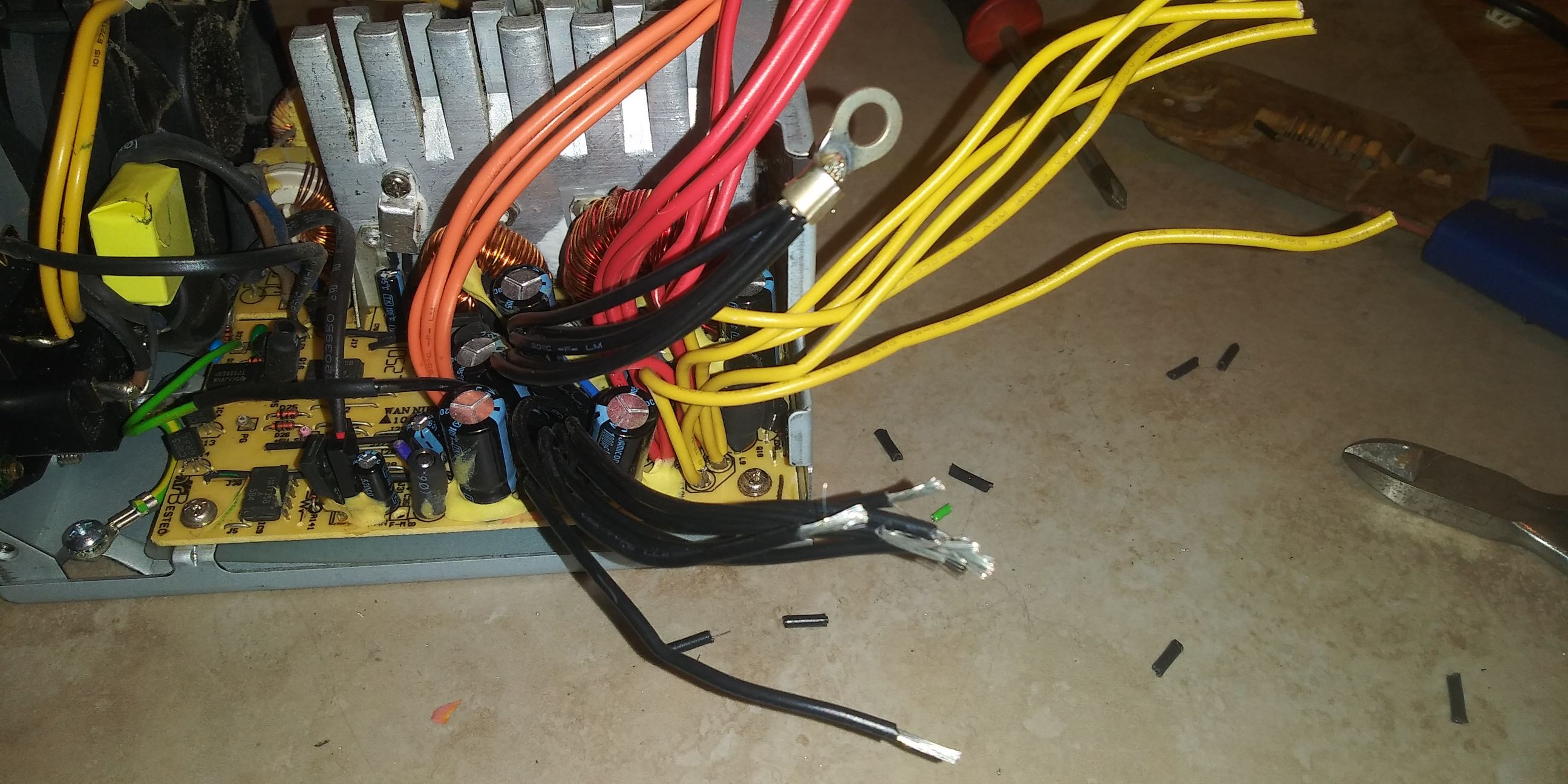
ONLY the wires that are in the bundle that goes outside the case should be cut. We’re going to keep the Red, Yellow, Orange, Black, and Green, but cut them off long. All the others should be cut as close to the board as possible. This keeps them from coming into contact with anything else. FYI, this is the Blue, Purple, Grey, and Pink. Remember, ONLY the bundle wires, the one that didn’t originally leave the case must be left alone. It also helps to gather the colors together.
Optional. The Purple wire is 5vsb (stand by). It’s always on, when the power cord is plugged in. You could use it for a power LED if you are so inclined. You could also LED one of the voltage wires, but that will only indicate when turned on and powered up. Might be useful if you have a switch.
The Green wire and a single Black wire should now be cut to length, soldered together, and heat shrinked. Pic doesn’t show heat shrink.
Optional, Put a switch between them and mount it in the case. Now you can power on / off without unplugging.

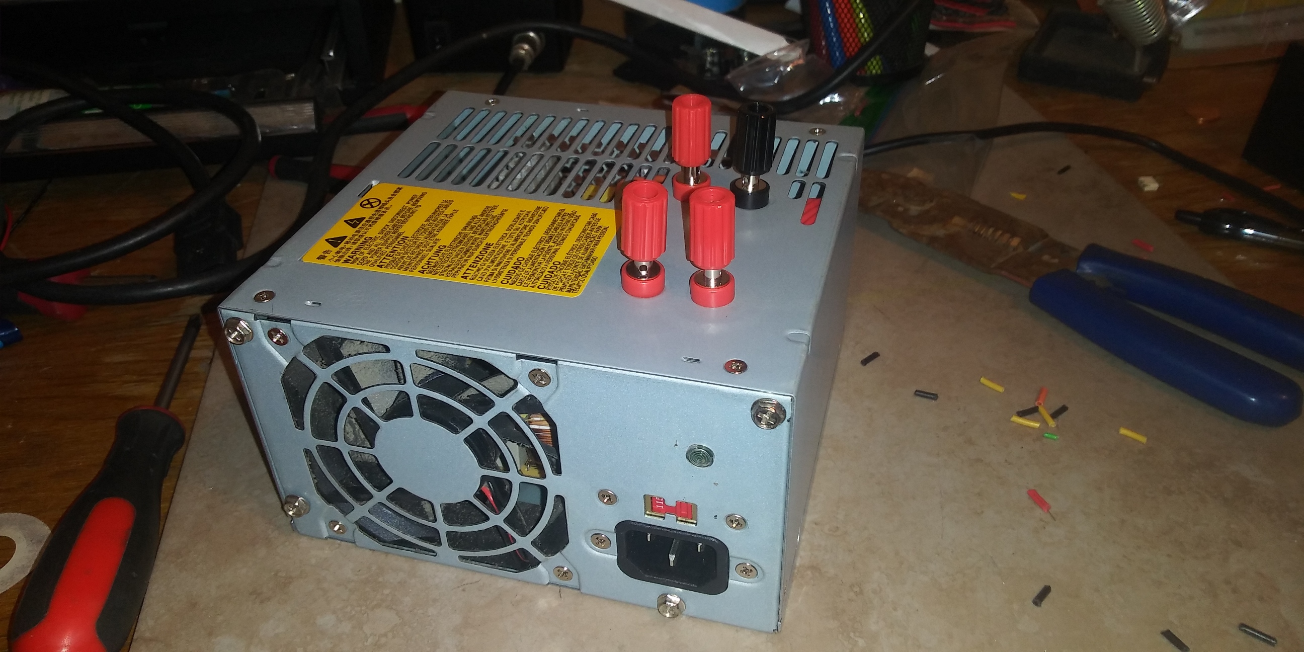
Ok. Now back to the cover. There are open areas inside the case. It’s necessary to drill 4 holes in the cover that will be over those open areas. There are drill bits for use in sheetmetal. Unibit is the brand that comes to mind. Regular drill bits will make a jagged mess. Time to install 4 Nylon binding posts. I use them from Radioshack, cause they’re the cheapest I’ve found. For those who don’t know, binding posts are an incredibly easy way to connect a small wire. You just unscrew the top, put the wire through the hole in the side, and jam the top back down. Works great. Exact locations and colors are optional.

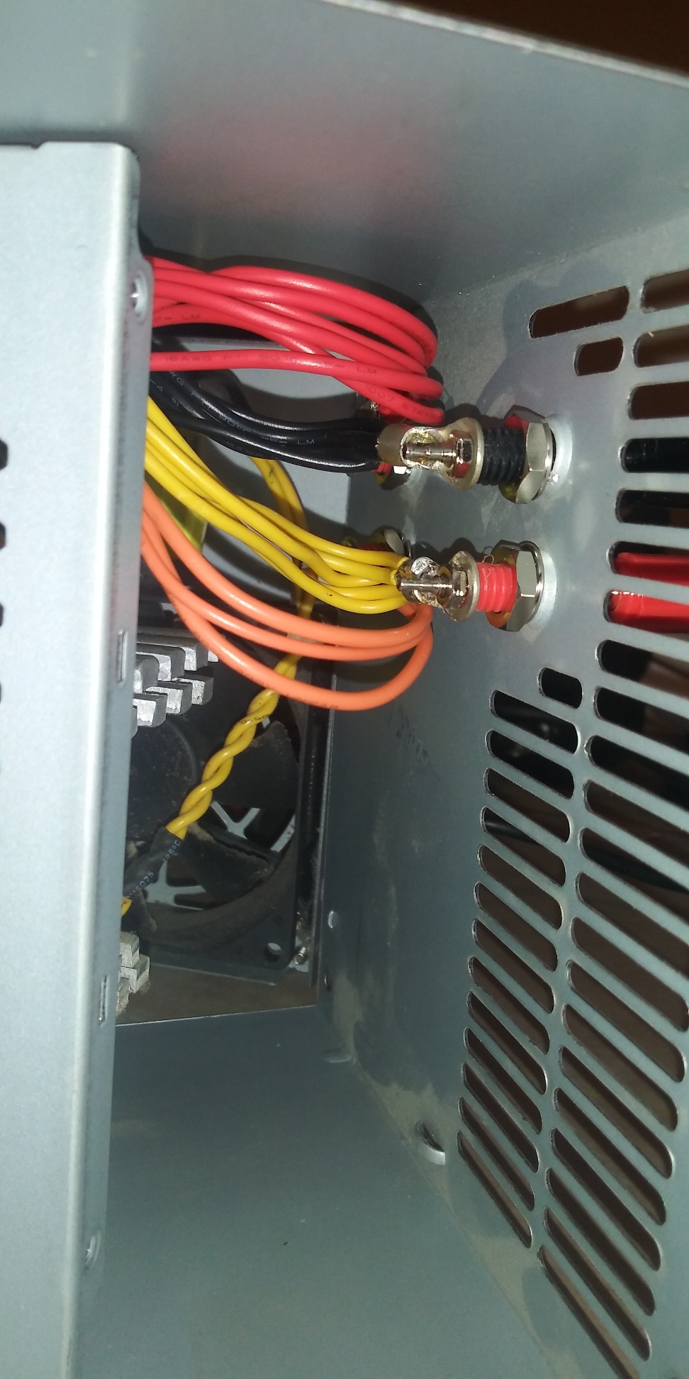
Now that we know where the binding posts are going to be, time to cut the wires to length and solder a terminal on each bundle/ color.
Note. Sometimes you’re gonna have more wires than you can accomadate. It’s o.k. to prune a few. (see black wires in pic) I used the large (yellow 10-12 gauge) terminal with the insulation sleeve removed.
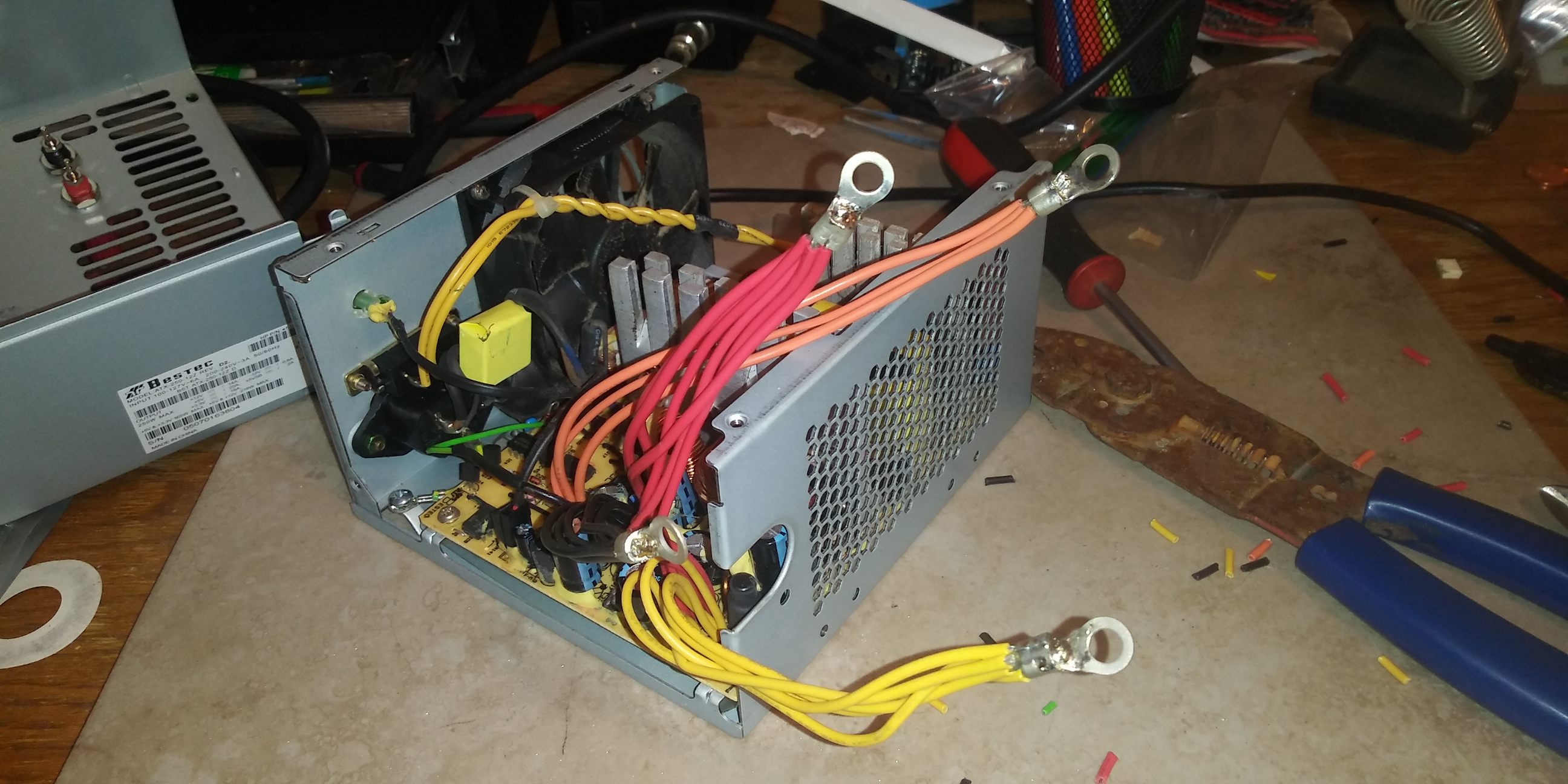
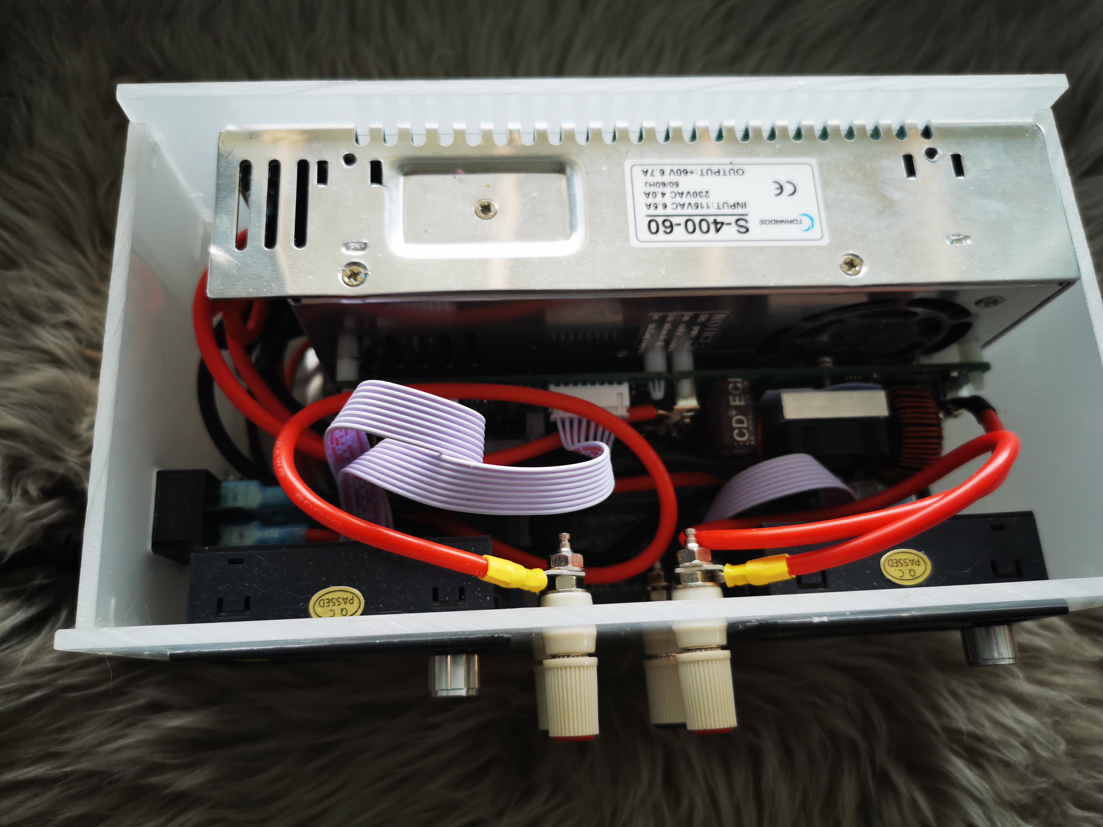
Now it’s time to connect the wire bundles to the binding posts. Wire length is a tricky balancing act. You want short, to keep it neet and workable inside, but you gotta reach in there to attach the terminal too. Don’t let the terminals touch each other or the case (duh, right?).
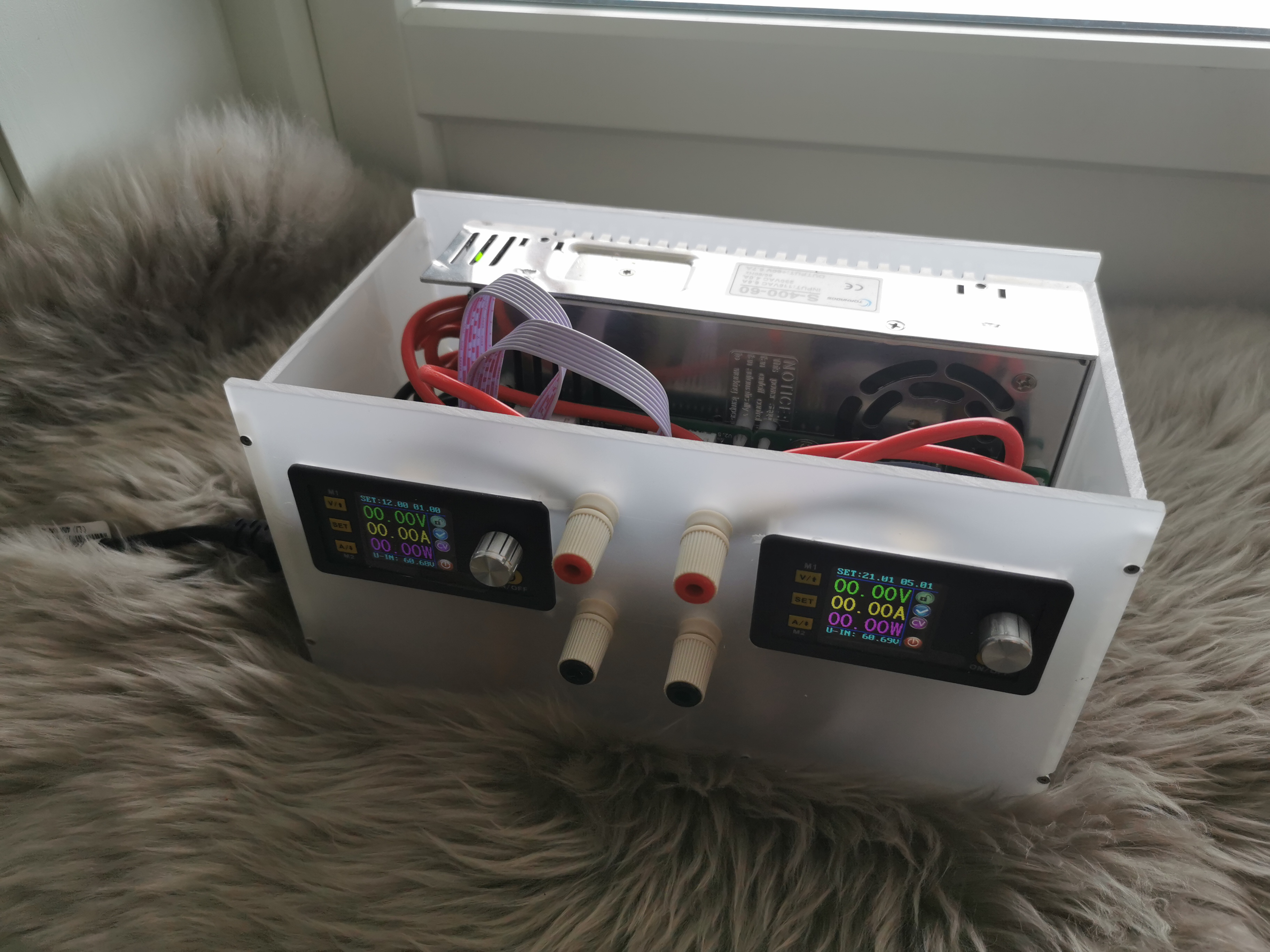
Put the cover back on. Make sure everything lines up, and BE SURE the wires don’t get pinched.
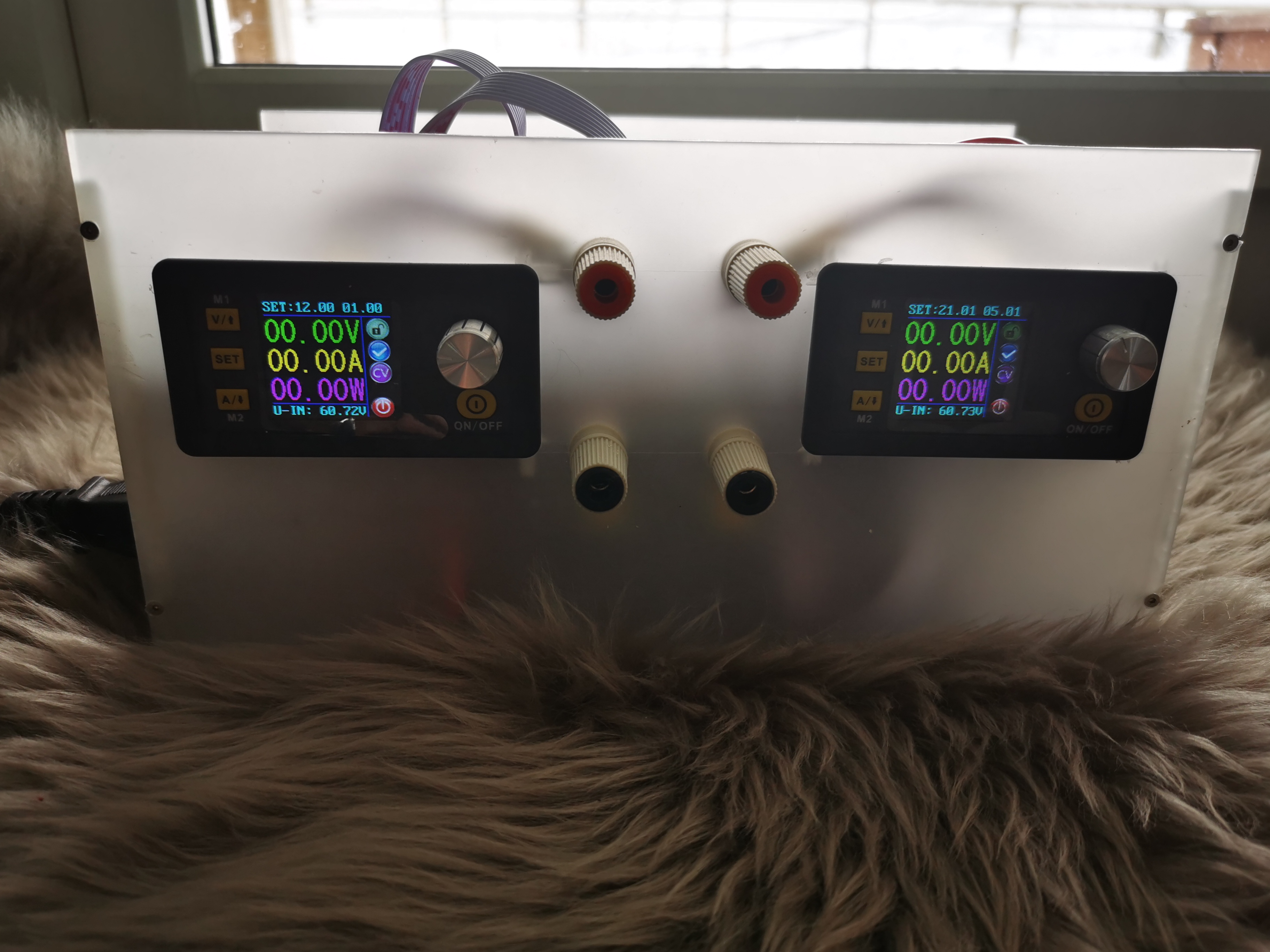
If you got something like this, Congrats.
And that’s how I make a low cost, yet extremly useful and durable benchtop power supply. Seriously, don’t abuse them and they last forever. At least I’ve never had one go bad.
P.S. Get a sharpie and label the binding posts to their voltages.