Although I do have other reasons: when I ask about read range, I’m indirectly trying to assess how well it couples with the reader’s coil, because I’d be interested to make that thing work for me. With my M1k - which, for a glass implant, is quite a hard hitter - it won’t wake up no matter what. I’m sort of hoping a Flex would.
Also, if it made it a bit easier to trigger my Yale Doorman, that would be a plus too. While I can open my front door with the glass Mifare, it takes great skill to stick my hand at precisely the right spot.
Okay that’s good to know.
I guess I’m luckier than your with my glass implant, because it’s much less finicky than that. Most phones require me to be within, say half an inch of the magic spot. But once I find it, it hits easily each and every time. And usually it’s not that hard to find, because it’s either around the camera lens, or over the battery. So I guess my own experience makes me a lot less easy to please with potential improvements
It’s tough to think about these abstract field behaviors in a tactile way. Read range is not linearly related to the size of the coil. A 4cm diameter circular coil will not read from twice as far away as a 2cm.
Additionally, most of the flex implants do not have a circular coil (which is the ideal shape for coupling efficiency). Most flex implants have an elongated coil of approximately 25mm length and 4mm width, to get the best performance with the least install difficulty. The length doesn’t primarily increase the read range, it primarily helps with coupling orientation. If you’re solely examining the read range, the flex implants mine as well have a 5mm diameter circular coil.
Hopefully that helps explain some of the perceptions about the performance.
This can never ever be the case because it takes two to tango, as they say. The reader antenna shape and power output are what creates the shape and size of the magnetic field that the tag antenna must couple with. You can never have a tag that is universally good for every reader… except when every reader is designed to work with specific tag antenna shapes (like ISO card dimensions)… in fact, the ISO14443 standard has several parts, and part 1 specifically deals with antenna shapes.
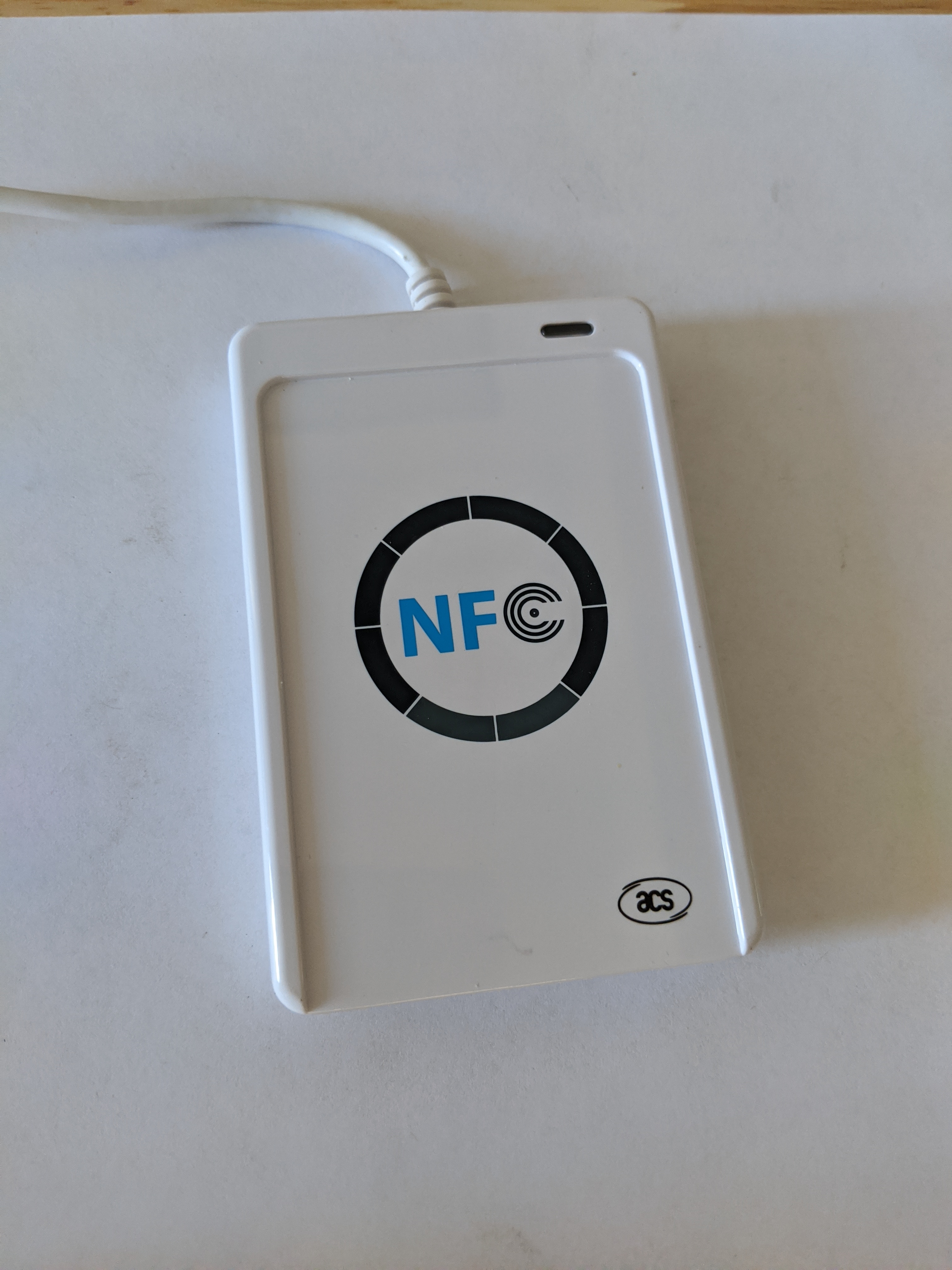
The ACR122U has a very VERY interesting coil design… it’s sandwiched between a ground plane which is something I’ve never actually seen in use before in my life… but the result is a very specifically shaped magnetic field that is REALLY good within a short range. You will notice that the reader plastic actually has an indent on the face of it the size of an ISO credit card… this is so contactless cards can be dropped into that indent and have a ROCK SOLID coupling. Other shapes, not so great at range, but if you position them correctly, they too will have a very solid connection, just not a lot of range.
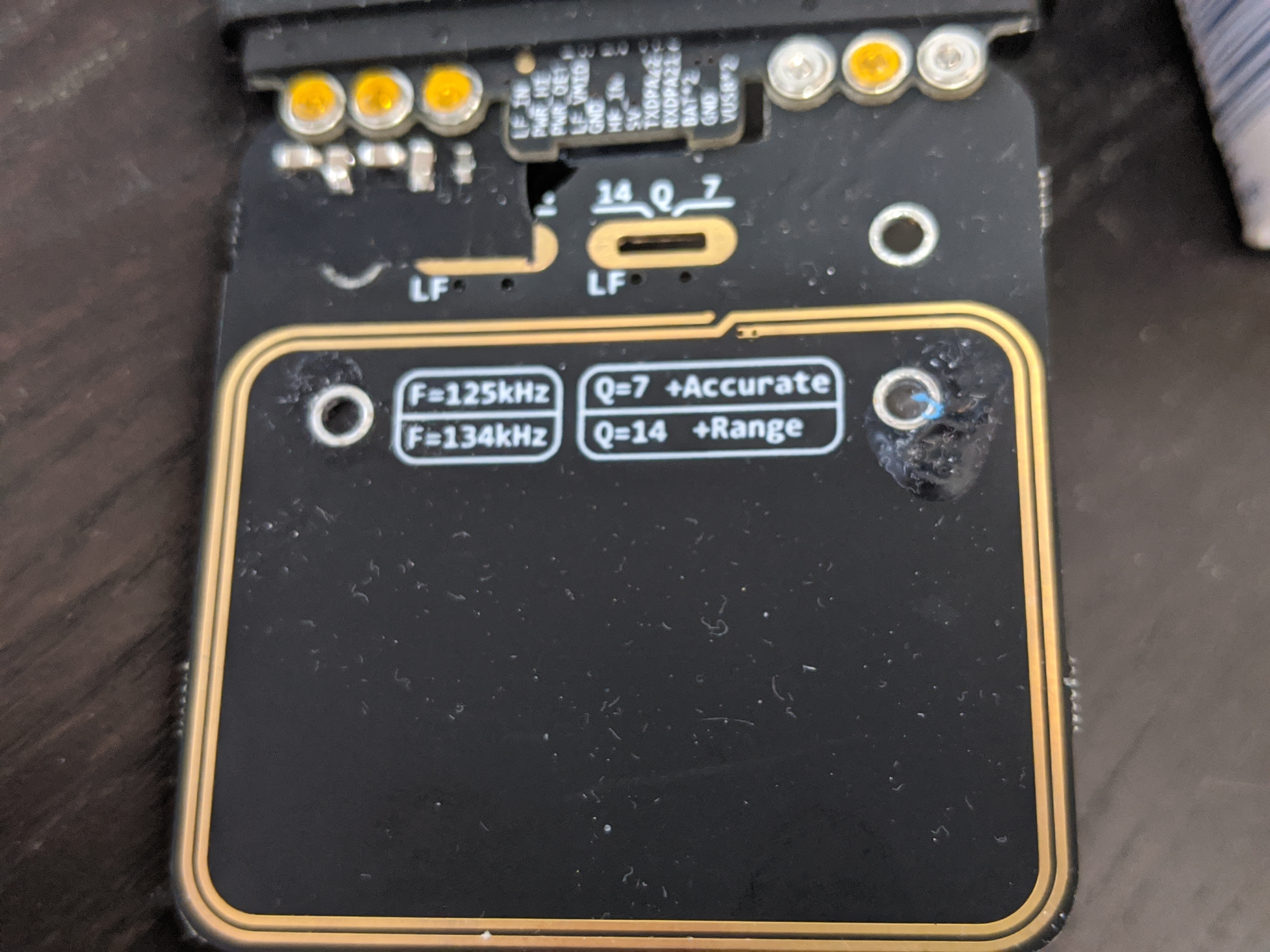
If you want to study the black arts of magnetic field coupling, look into antenna Q factors and how that can affect range vs coupling quality… in fact, the proxmark3 rdv4 LF antenna even has switches to change the Q factor of the reader antenna so you can choose range or accuracy (low noise) of the coupling … and these switches do nothing to the power output, they just change the harmonics of the antenna itself to adjust the Q factor.
All that said, the best general antenna shapes for tags is one that is equilateral, meaning circles and perfect squares typically have the best chance at coupling with most basic flat spiral plane or flat circle / square reader antennas. That has a lot to do with how the lines of flux cross the antenna and what effect they have in which direction. To make the flex implants easily implantable, we squish that antenna down into a long narrow run, which reduces the orientations in which it will couple well with most reader antennas… effectively giving is a “sweet spot” where a perfect circle like the flexEM has a much broader area with which to couple to a reader’s field.
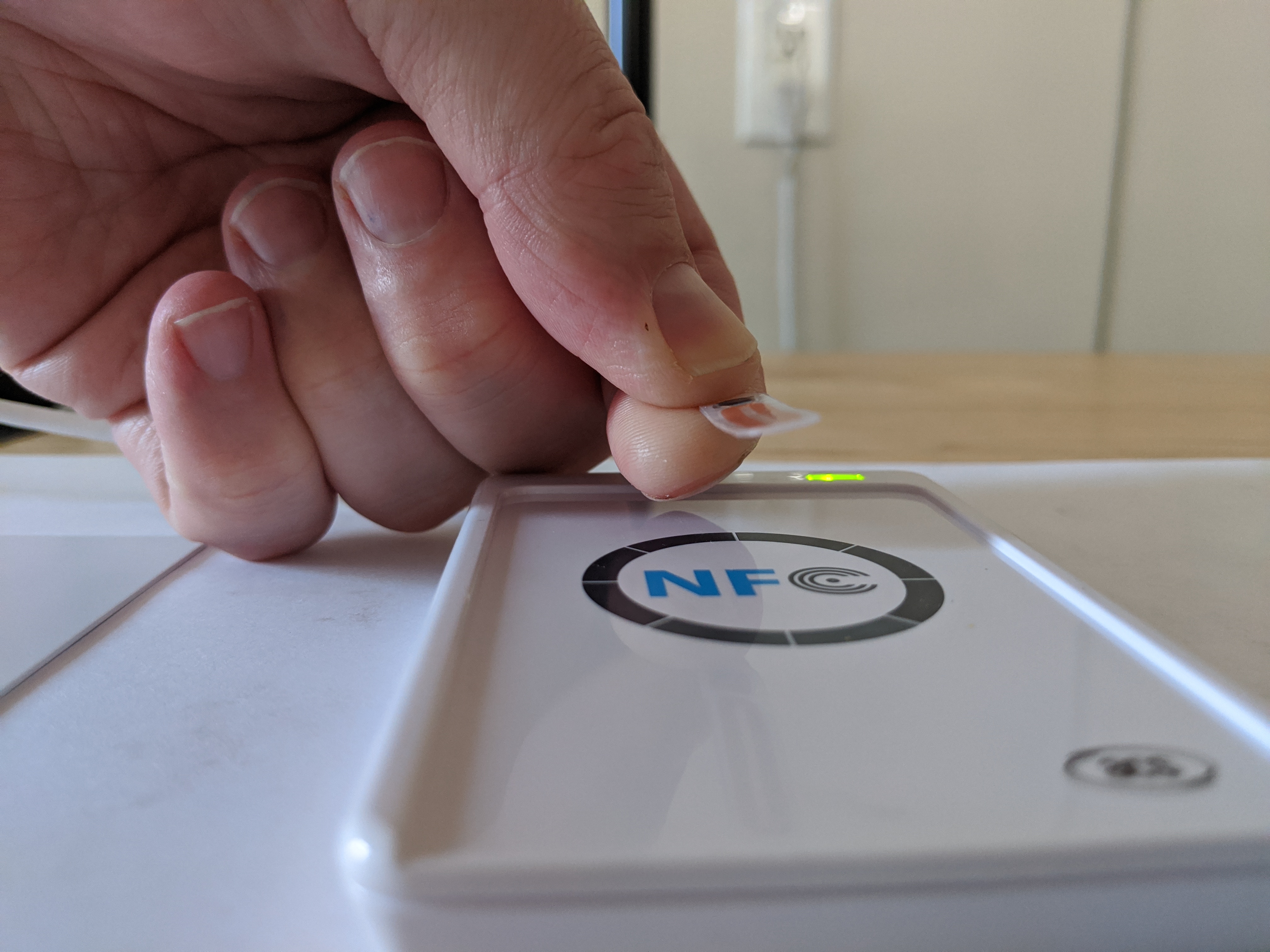
This is a real test with a flexM1 gen2 which is working at 2cm (20mm) above the face of the reader. This is exactly half of the 4cm the “perfect” full size ISO credit card gets on the same reader… so I’d say range is great… it’s just that unlike the card, range is affected by position and orientation.
You misunderstood me. Of course antenna shapes and orientation matter. What I meant to say was that I was comparing the best read range in the best orientation for a given transponder/reader combination, on the same reader for two different transponders, so I can get variables out of the equation and only compare the read range difference between two transponders.
It may seem pointless to compare read ranges that way. But look at it from a practical perspective: if you want to get a stubborn reader or cellphone to read, you have to find the best spot and twist your hand into odd shapes - which means, in reality, that you’re positioning / orienting your implant to get best coupling anyway. So if you already know transponder t1 reads at max distance d1 and transponder t2 at max distance d2 in the best case scenarios, maybe you have a chance to guestimate whether or not transponder t2 has a chance to trigger that reader that t1 doesn’t.
At the end of the day, what’s really needed is measuring instruments and samples. But absent that, the “tool” I’m working with to determine if a Flex implant would trigger an Idesco door handle before buying said door handle is your internet forum, the forum dweller’s good will (thanks you guys for the wealth of information by the way, this is really rare and noteworthy on the internet!) and their subjective feeling on how well this-or-that implant works. Hardly scientific…
This is much more in line with what I expected to see. So it does look like Satur9's Flex has a slight problem after all Just kidding…
Lol. 2cm off the reader does comport with my brief experiment in the video, though. I was roughly estimating 8mm off the surface of my skin, but there’s at least 5mm of slightly attenuating flesh in the way, and I didn’t perfectly position the reader, and it’s a flexDF not a flexM1
Hi,
per our private discussion I did some research on this with my Gen1 and Gen2 cards and here are the findings.
So the idea is to write incorrect access bits to sector trailer and see what happens. I used Amal’s document as a starting point for good access bit values: http://amal.net/wp-content/uploads/2012/11/NFC-Access-Control-for-Mifare-S50.pdf
These are good, valid access bits: 787788. I then modified a single bit to get invalid values:
797788 - invalid inverted bit for block 0
7A7788 - invalid inverted bit for block 1
7C7788 - invalid inverted bit for block 2
707788 - invalid inverted bit for block 3
786788 - invalid “regular” bit for block 0
785788 - invalid “regular” bit for block 1
783788 - invalid “regular” bit for block 2
78F788 - invalid “regular” bit for block 3
More invalid combinations can be generated. I tested with the above to “cover” scenarios when “regular” and inverted bits are invalid.
Gen1 findings
Messing up access bits does indeed lock the whole sector for reads and writes (with either key A or key B).
Other sectors on the card are NOT affected by the messed up sector. Reading other sectors on a card works fine with regular Mifare commands.
Chinese “magic” commands can still read everything normally - even when access bits are invalid!
Chinese “magic” commands CAN easily fix invalid access bits. Just write valid access bits to sector trailer and done. Previously written values in data blocks are preserved.
After fixing the sector with the chinese “magic” command, data blocks in the sector can normally be read and written.
Gen2 findings
Writing invalid access bits locks the whole sector. Can’t read with either key A or key B. Proxmark returns an error:
#db# Auth error
failed reading block
Reading from and writing to other sectors on the card still works fine. Messed up sector does NOT affect the whole card.
If sector access bits are messed up, it’s game over for that sector. It’s locked forever. I was unable to find a way to fix access bits with neither key A or key B.
By “memory tear” you mean repetitive reads and writes (like hundreds or thousands of iterations). Thousand writes goes well, and then on the 1001st write the card erroneously writes a single invalid access bit and the sector is locked?
I guess this can happen… but my uneducated guess is these scenarios are more likely to happen:
A user plays with the card and writes invalid access bits
I think what @amal meant by tearing in the context he used it is what @Dean is thinking.
As in if an erroneous bit gets written to the sector trailer by a coupling accident or a writing hardware glitch, is it recoverable?
From looking at @franskav’s very detailed post (great work, thanks for such an in depth write up!) it seems the answer is that Gen1 is pretty safe and unbrickable, but Gen2 can possibly be bricked more easily, so it should be treated with care when performing writes.
Does that conclusion seem to match what everyone is thinking?
Yes, this is my sentiment as well.
I bought a flexM1 gen1 and personally would never implant a gen2 knowing sectors can brick (either my mistake, hardware mistake or whatever).
@franskav thanks for that really informative write up.
I do like the convenience of being able to write with my phone. I will still be getting a gen2, it’s worth the risk for me. If I brick it, I have done so knowing the risks, Thanks to your great write up and Amals posts.
IF that happens, I’ll then look at going to a gen1a…maybe
Do YOU think I have used enough BOLD in this post?
No I would have added some more if I were you. I do like the convenience of being able to write with my phone. I will still be getting a gen2, it’s worth the risk for me . If I brick it, I have done so knowing the risks, Thanks to your great write up and Amals posts.
IF that happens, I’ll then look at going to a gen1a…maybe
Do YOU think I have used enough BOLD in this post?
There that looks better LOL.
Correct… a “tear” is a break in the writing process that causes corruption… this can happen with any media… for example, when a hard drive loses power during a write that leaves a particular sector corrupted or a file table out of sync with drive contents, or in the case of a chip implant if power is lost or more likely insufficient to perform safe writes. Passive chips are difficult to assess because reading a tag requires far less power than writing, so you might read a tag just find and think “I have a good coupling” and then attempt to write and suddenly your power transmission is insufficient to complete the write and it tears.
I consider a noisy connection, be it wired or contactless, to be a different kind of problem… not a tear, but data corruption in transit. Usually transport mechanisms have checksums and other methods to detect and handle data corruption in transit, but unless the memory blocks being written have anti-tearing built in (some chips do for certain critical memory blocks), a tear is basically a 100% certainty if you have power supply issues.
I once worked on a shot counter product that was self-powered by the recoil of the firearm. There was a strong magnet inside a coil, that would shuttle back and forth when the gun was discharged. It would power the device briefly (up to 14 ms if I recall): in that time the processor would power up, read the current counter in FeRAM, increment it, then write back only if the voltage was above some value. We only have some dozens of CPU cycles to work with - minus the FeRAM’s read and write cycles - so the code was very tight.
It would miss shots if the shooter held the weapon too tightly (not enough recoil) but it would never corrupt the counter. We made damn sure of that.