I wonder how this translates to eyeborg, I wonder if it’s possible to email images and him upload them as camera signal
… then I suppose you are back to square one with different cameras lol
Not a full derail, as yes my xSIID is quite bright, I guess I can’t say brighter than others because aforementioned visual biases, but it is definitely not being absorbed quickly, as I can see it illuminate .394 inch of the surrounding flesh when powered
Color, brightness, luminosity… are things that are surprisingly difficult to measure.
I learned that years ago when I worked for a small arms supplier: our customer complained that the pistol holsters we had supplied didn’t conform to the desert brown they had requested. Since we had no real acceptance criteria other than “it looks similar to the reference model”, I was tasked to find a metrology supplier and a procedure to measure the color objectively.
That sent me down the rabbit hole - DEEP down. I ended up visiting all kinds of scientific labs, fabric manufacturers, certification agencies… and spent north of 50k euros on test equipment and third-party colorimetry, to end up with not very many conclusive results that wouldn’t have ended up making the cost of the holsters spiral out of control.
In the end, we produced a 200 page report on the subject to the customer, and we mutually agreed that one guy comparing the production to a reference model in decent daylight without too much alcohol in his system was probably gonna be as good as it’ll ever get
Here’s a 45 minute video you can send them too if you want to blow their minds. As you no doubt would have come across, lighting makes it hard to determine the true colour of something, but the reverse is also true - different objects make it hard to get lights to look consistent.
Here’s a great video with demos of how two colours that look the same can be entirely different in the world of theatre lighting.
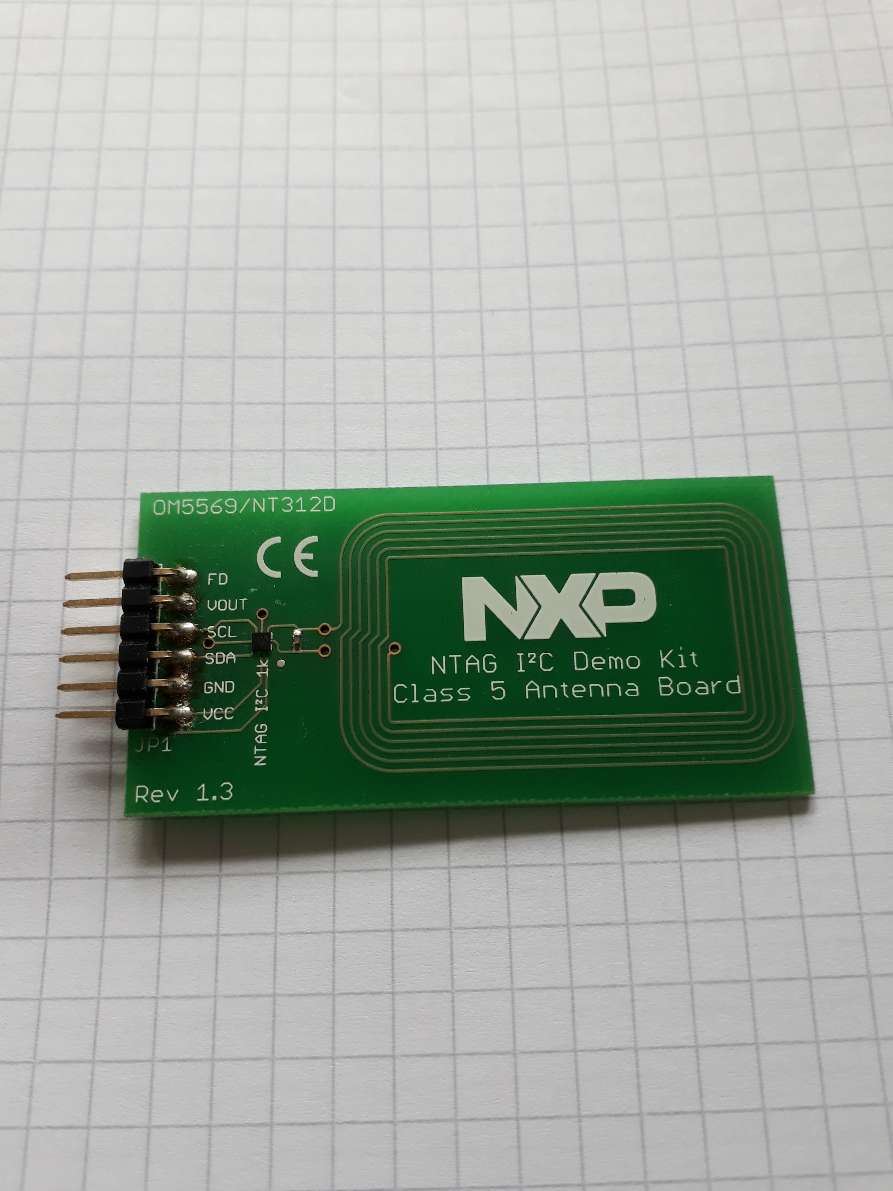
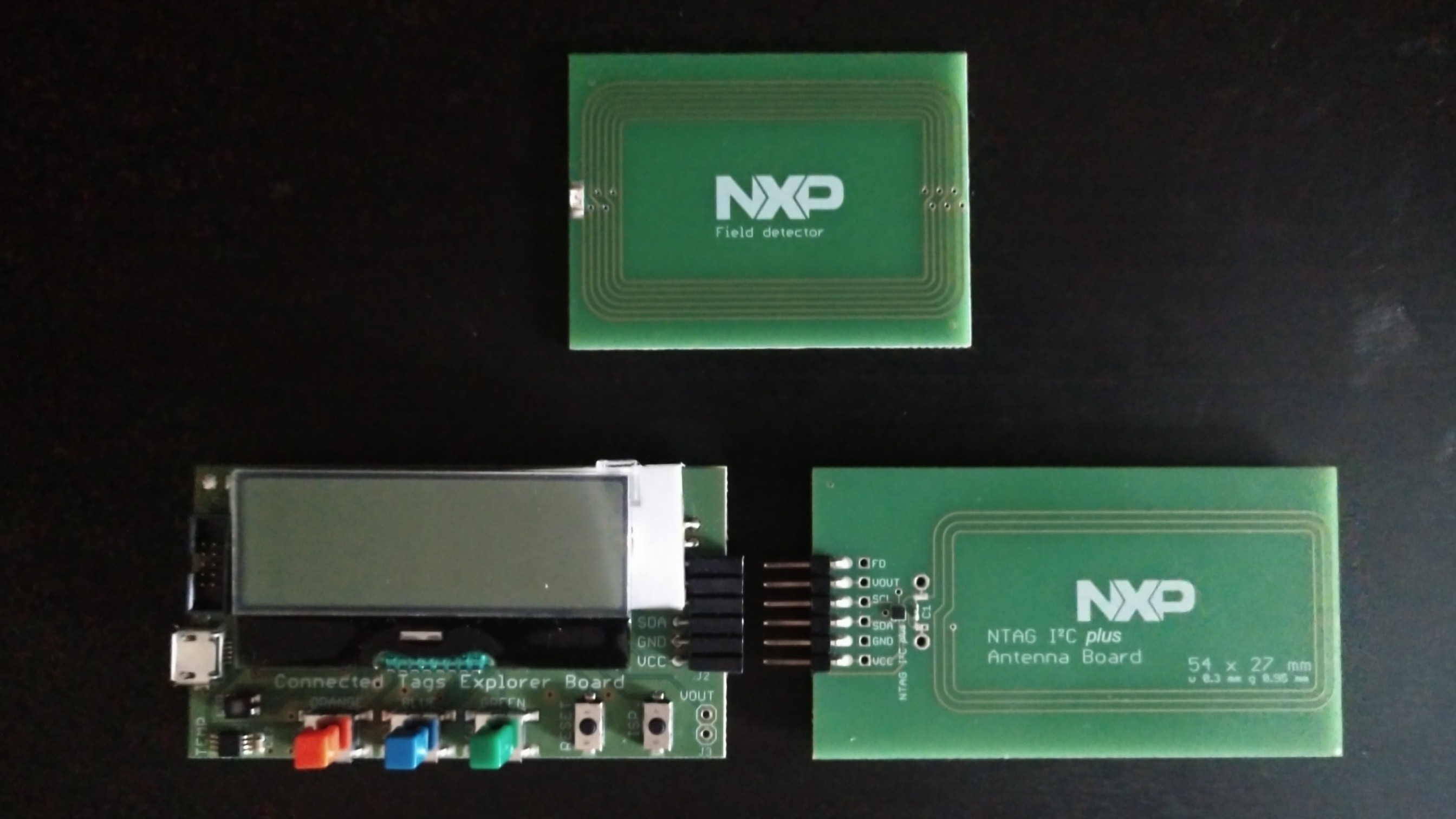
@Satur9…as I’ve just found it, for info this is one of the NXP NTAG I2C demo boards. It consisted of a second board with uC etc. Put that somewhere safe years ago. Think NXP currently do some flexi thing with the device mounted.
It’s a nice little kit. They have some interesting antenna designs on their dev boards. Each concentric trace in the antenna is going the opposite direction because of some clever via routing.
Unfortunately I got my hands on one of these kits after I designed my business card based on the NTAG I2C Plus. It worked out though.
Oh almost certainly the RF engineers at NXP, with $100k+ in analysis equipment and simulation software, wouldn’t do all that extra work for no reason.
Now what the point is would be a bit more difficult to nail down. It could have to do with eliminating parasitic capacitance between the traces to allow more accurate estimation of the inductance value while designing. If you review this test board I made you’ll see that the coil design where I split half the turns on the top of the board and half on the bottom was spot on to the calculated Inductance using NXP’s formulas.
It makes sense that they would need that accuracy for the field detector board, because there’s no tuning capacitor, the LED is the the tuning cap (and a small one at that). Doing it this way could also present a lower impedance so that more power could be delivered from the reader, which would also make sense for lighting an LED.
@anon3825968@darthdomo Only other thing I wanted to add was that I did check out Amal’s post you linked and I totally see what you mean and how he credits amber to be the dimmest, but I would like to also point out he’s saying that in reference to the 4 different colors of the same LED, which at that particular brightness, or with that particular line-up of 4 LED’s that the green was brightest and that Amber/Red was the dimmest. I can’t tell for 100% certain if Amal was implying that that applies to all implantable LED’s and their relative brightness beneath the skin at any intensity, or if he was just applying that fact to those 4 LED’s and that is not a rule that holds true with all implantable LED’s in general.
I’ve been busy with work stuff so not had chance to do a great deal on this but I’m back on it! @amal I’ll contact you on the weekend. I did plan on doing a full-on video but anything I’ve got camera wise just doesn’t deal with bright LEDs very well, no matter what settings I play with. Also I can’t be spending too much time on film production. Just a couple of things to optimise but it is basically there. Flags seems to be the theme! As I’ve a fair selection of LEDs I did try a rainbow version but the let down is the purple. Well you’re in UV territory really and they ain’t particularly bright given the constraints of the available harvested energy.