The anti🚫-derailment🚃 & thread🧵 hijackingšŸ”« thread🧵 ⁉

9.6
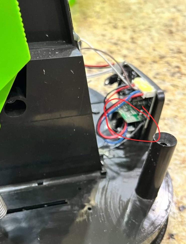
Battery looks to be 3 18650 cells or something similar… I’m sure there’s voltage voodo tho…

I’m guessing this things toast at this point, I’m only annoyed because I made sure it worked and got my dog excited for it, and then it decided to self terminate before it even got used

1 Like

Nominal is 3.7V, but charged is 4.2V
x 3
It will be a 12V supply

2 Likes

No, the negative is the side with the cross hatch.

If you want to get an ElectroBOOM moment… Check the voltage across it with a multimeter and you’ll see that it’s either correct or completely dead. Electrolytic capacitors will work backwards, just not for long.

The original capacitor had a voltage rating of 16V, that’s a maximum. So you’ll need a 12V power adapter and I’m starting to think that I know why that capacitor exploded… Let’s hope that power supply didn’t take out anything else.

This would still be incredibly helpful, I managed to find some information off an Amazon review but more details would be extremely helpful.

Li-ion? In series? Without a battery management system?

:emoji_mindblown:

Apparently, some units have a second board, can you post pictures of how everything goes together?

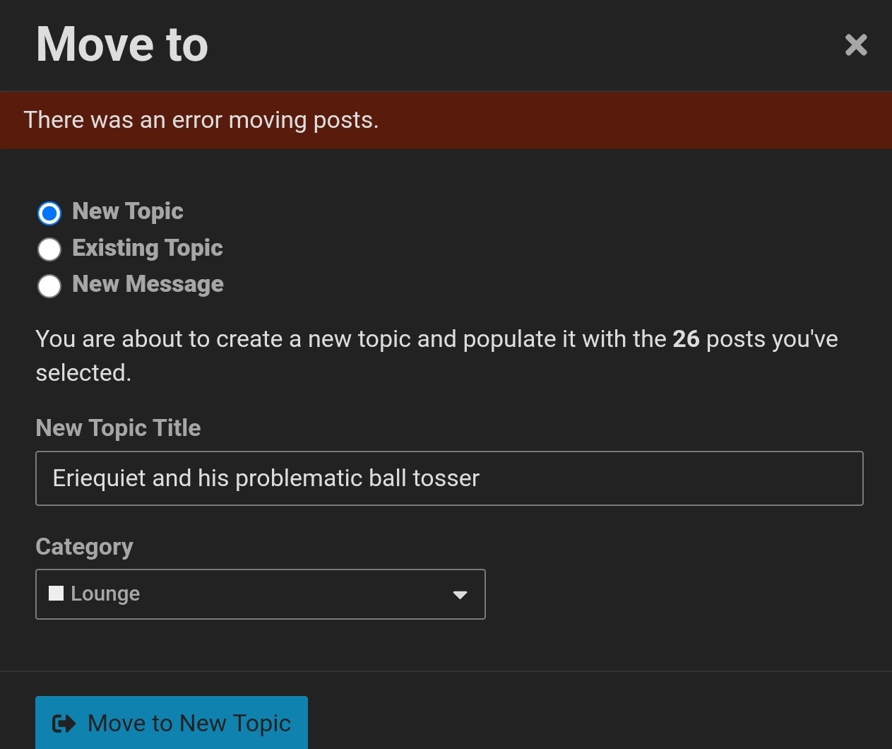
Also, is it ok if I ask the forum AI to move the dog ball launcher posts into their own thread? It’s getting a bit hard to navigate.

1 Like

Funny, now I know why something I thought was a spark plug didnt look right.

2 Likes

Oh god no! You’re supposed to smoke the cotton swab, drink the alcohol and then clean the pcb with your heightened state of mind.

3 Likes

Yea I’ll post in better detail,
I have to try to fix my lawnmower today,
Hopefully I’m less of a bafoon with that… but we are on weekend 2 already… so that ship may have already left the port

Hmmmmmm

Not sure what the problem is
I’ll give it another try a little later

2 Likes

Ladies and Gentlemen, prepare for the FLEX.

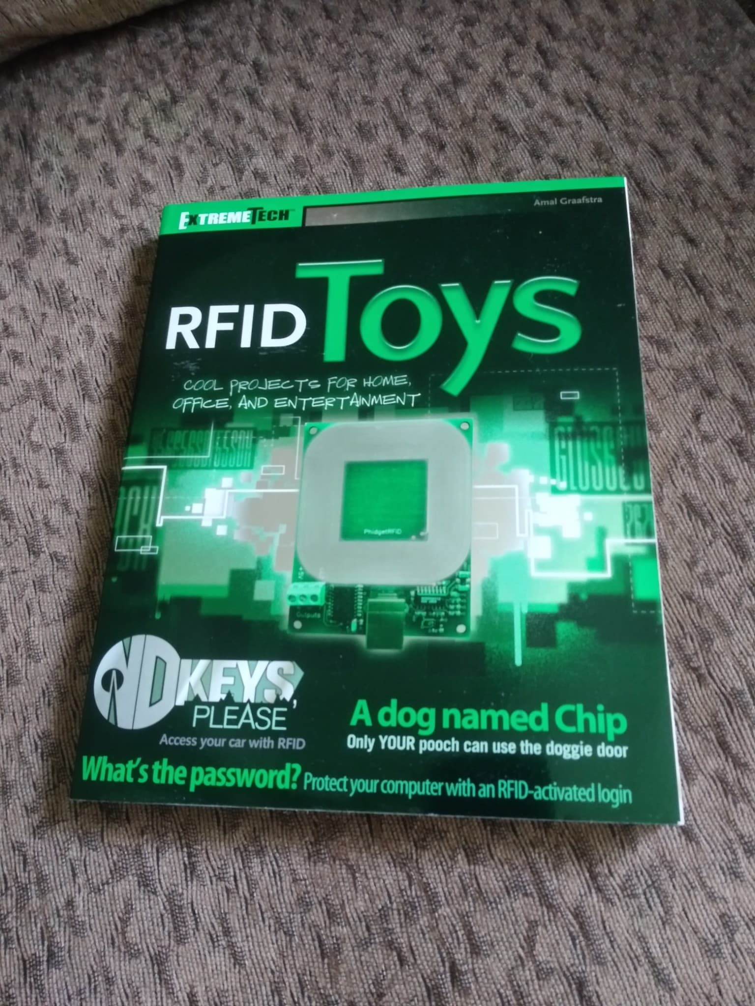
'Cause not only did this show up in brand new unread condition:

But this was very graciously added to it.

11 Likes

Bruh leave some clout for the rest of us damn…

5 Likes

8 Likes

Well I at least managed to fix lawnmower today, that helps me feel better at accomplishing something

I’ll probably sit down and have time to document that board layout if you want @enginerd

That being said, suspecting now that it was overvolted… what are my chances I didn’t blow the rest of the board in the process? Kinda don’t wanna waste your time if it’s a lost cause

3 Likes

I honestly thought for a significant amount of time that said an ā€œaverage forum memberā€

I didn’t know how to feel about it lol :joy:

8 Likes

Over 48 hours later, so officially missed day, not bad timing and yet… less than 7 days, so not a missed day and I’m back on track! = One happy but confused LabRat.
So, sorry for the distraction and well done again StarGazer1258!

7 Likes

Hahaah omg… sick burn

5 Likes

Correction,
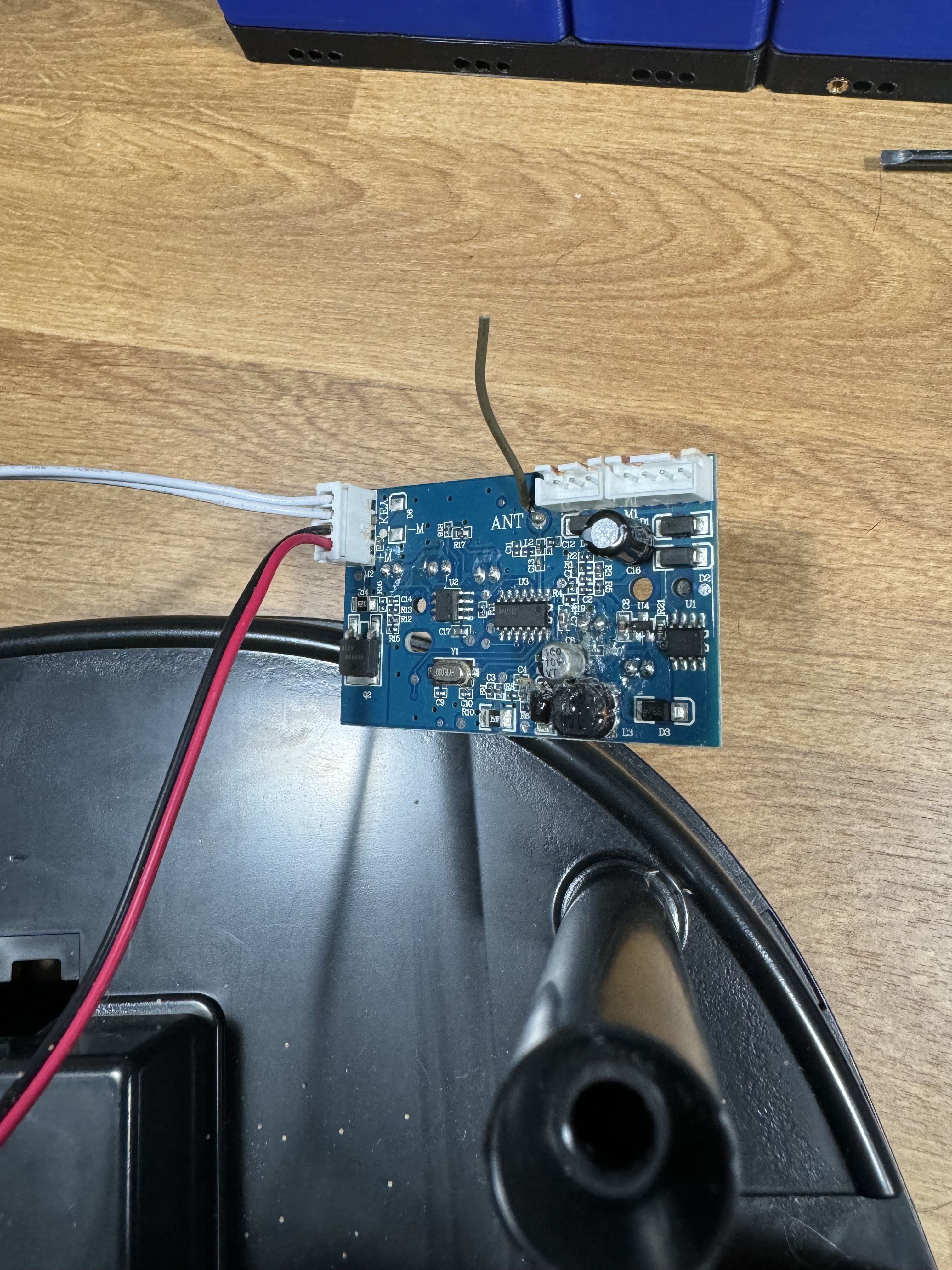
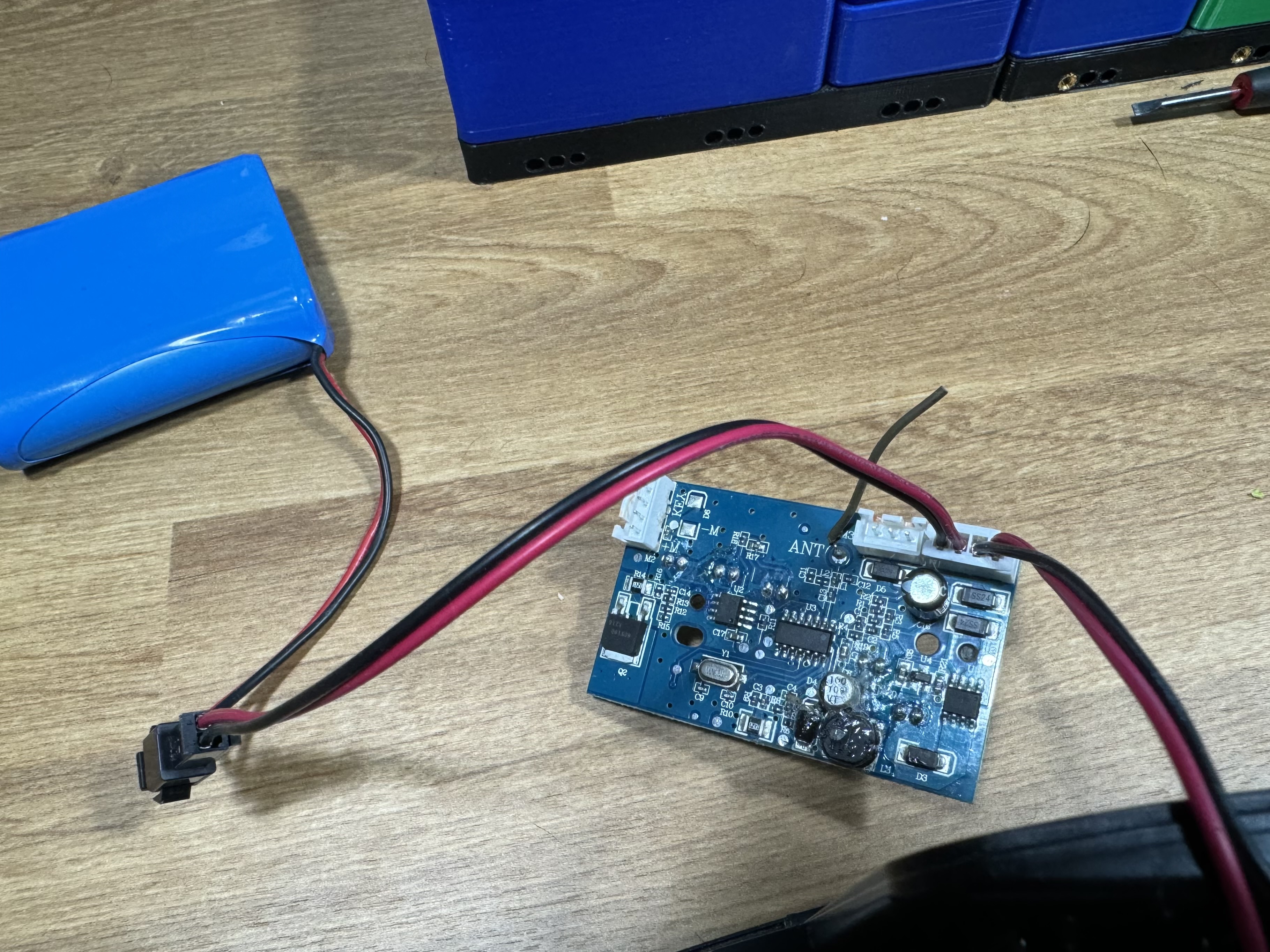
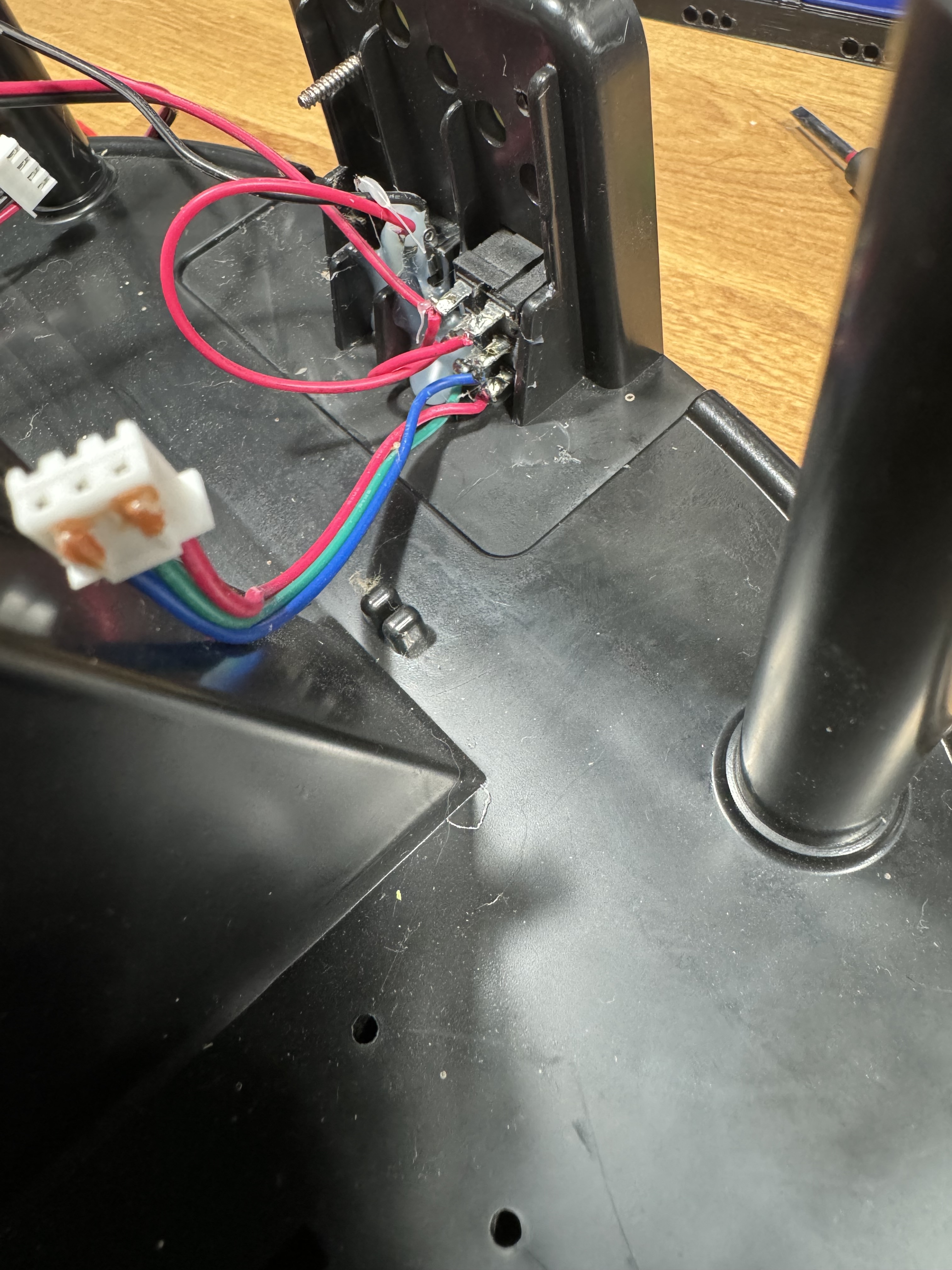
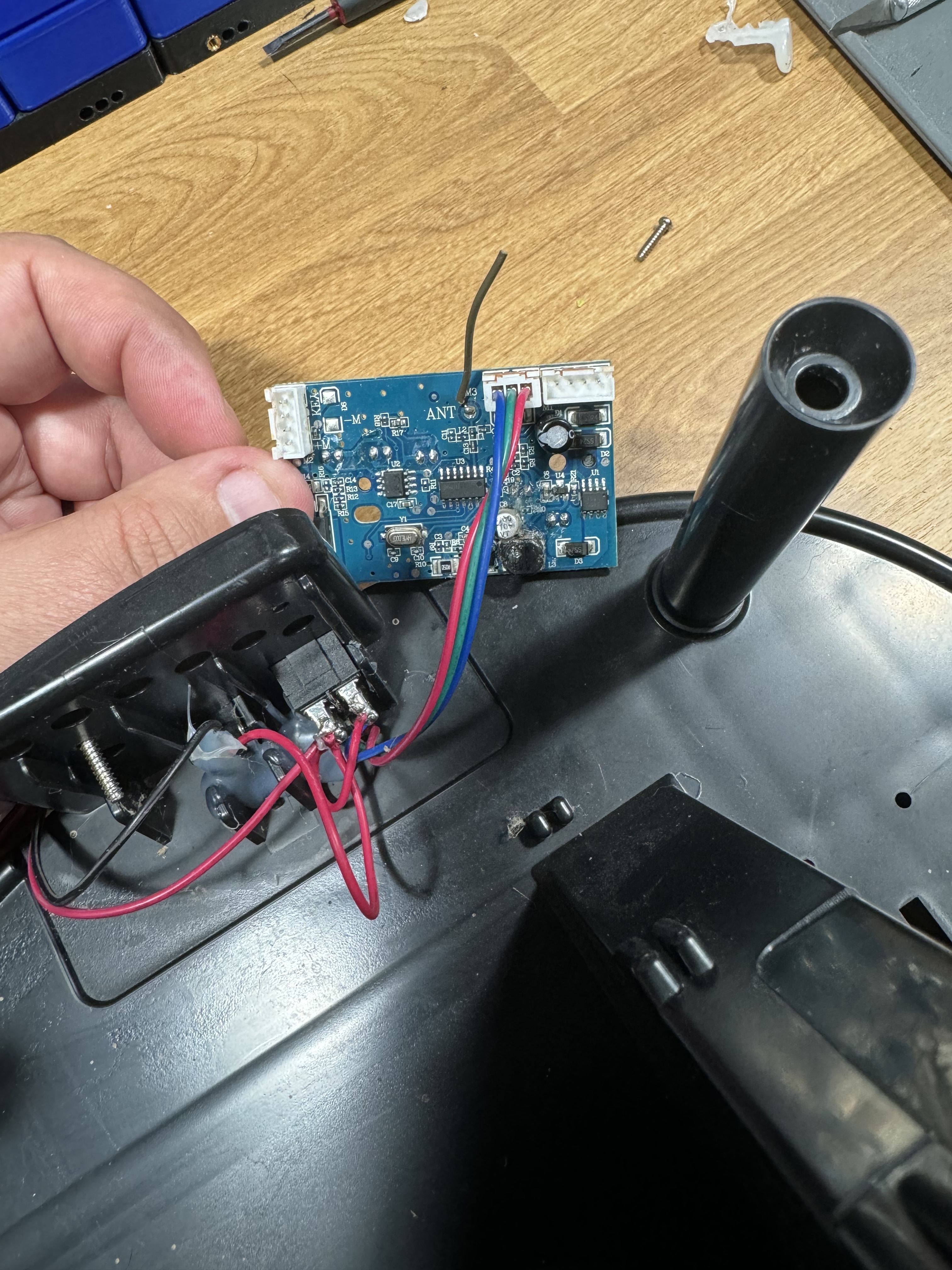
Mine doesn’t have the secondary board, the board I posted is what you get. All I have dc input, ball sensor switch, motor and battery connection


Ball sensor and dc motor


Dc in from switch, and battery connection


Coming off seemingly over complicated switch

At this point I’m just going to assume it’s blown and beyond my ability to correct… that single capacitor was pretty much the only thru hole component I felt comfortable replacing even if I was an idiot and had to figure out polarity

1 Like

Honestly, would’ve been cool with it. :sunglasses:

2 Likes

Sorry that I couldn’t be of any help.

1 Like
1 Like

@b42 if you are active on that blog, these are some thoughts for you to pass on if you would like

The poster is struggling for space,
Here is a simple ~8mm he can gain back with the use of a dremel or similar

This is not going to allow him to have it NOT protrude as in the picture, but for some of his internal options, that will be significant


~ With the 8mm removed, that fit will be easier, AND for this :point_down: below


Personally, I would do two things

  1. Desolder the micro USB port, and attach wires direct to the pads ( I would also do that approaching from the component’s side, explained why in the next step)
  2. Once the USB port is removed, I would remove the ~5mm of PCB where it used to lay ( if there is a struggle for height with the cable ontop of the board, then out the other way would still work, with the newly gained space.

This looks like the board is laying directly onto a foil sheet, I would get something to insulate the board from the foil, something like a ferrite sheet, like this

https://www.digikey.com/en/product-highlight/f/fair-rite-products/flexible-ferrite-sheets

Even thin foam or plastic would do, but not as good.

If it were my project, Those are the first tings I would try…or another NFC reader

@b42 It looks like you follow that project as you posted the original and an update here.

Please feel free to post further updates, It would be interesting to me, and probably the community to see how he gets on, It might well interest somebody here to make their own.

FIre any questions back from Terence Eden, or even invite him to join the Forum, where there are far smarter people than me than can help him out…


3 Likes