.. it’s not going to work for our purposes
The primary reason I looked into getting a Glowforge over another CO2 laser system was the bed camera and layout tool. Pretty much every CO2 laser system I’ve seen is a C&C laser head and some basic software. You place your target material on the bed and align your job file over the target material based on a pixel to distance ratio. For every pixel to the right or down from the upper left corner (0,0) means move the laser head N millimeters.. so if you have a ratio of 1px per 0.1mm and we put a square on the canvas such that the top left corner of the square sits at 50,100 (50 pixels down, and 100 to the right) then the laser head will move to 5mm down and 10mm to the right of the top left corner (0,0) and start firing the laser.
This works great for cutout and etching projects where you just toss a big ol’ hunk of whatever in there and blast it.. exactly where the pattern sits on the material isn’t paramount, you’ll have typically have a huge margin of waste material all around your target pattern.. so who cares.
This kind of set up is also great for jig projects where you create a design, position it how you need it, and blast away.. then the next time for the next run it will do exactly that same pattern.. so if you always have your target material firmly seated at 0,0 on the print bed you will always get the same laser pattern every time. This allows you to etch or cut out holes to make a jig in one piece of material, then you can place your real target material or object on to or into the jig, then run your real pattern and always hit the intended target exactly where and how you mean to.
The problem is, when I am making things I am using a process that does not lend itself to precise layouts. That means the target objects I need to cut or etch are going to be randomly positioned and aligned within my source material. That is why I wanted to work with the Glowforge.. so I could presumably use the camera system to view the print bed and my targets, then drag and align my cut patters over the targets embedded in the source material to a degree of accuracy that a salesperson I spoke to on the phone within Glowforge sales department assured me it could accommodate.
An offset problem
The reality is sort of a mix. The camera system is good enough that I can zoom in and place my designs around the targets with the required accuracy. However, there is an offset problem. The camera system in the Glowforge is a single fisheye camera mounted in the lid, positioned dead center over the print bed. That means to present a flat representation of the bed in the design tool, there are some algorithms being employed to flatten that image out. Unfortunately I think there are two problems.. first is that the algo probably isn’t perfect and has a % margin of error which only grows the further out from dead center you get, and it’s also likely that there are physical issues with the camera being mounted to the lid which has a large hinge it moves on and very likely some horizontal play sliding along that hinge which would throw things way off when attempting to position something to within 0.1mm accuracy. So how does that play out when we actually attempt to laser something based on the camera? Let’s take a look.
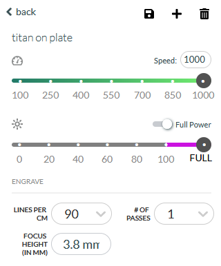
Camera calibration
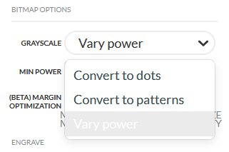
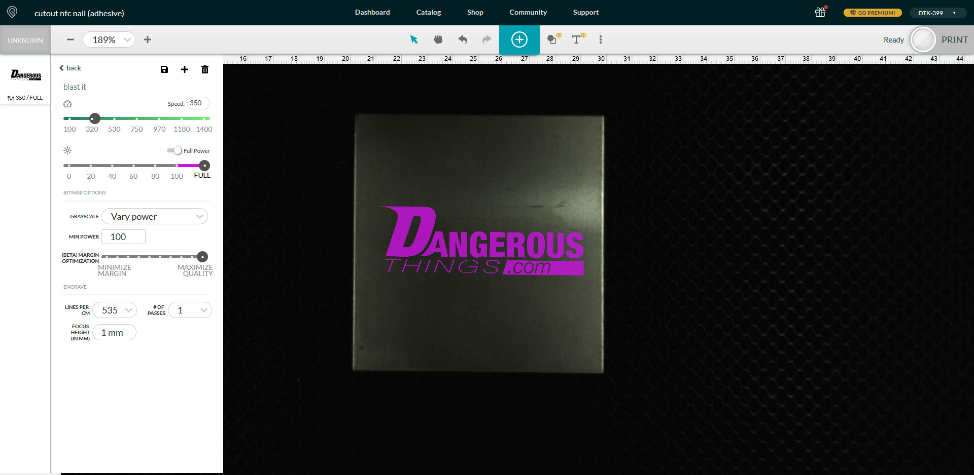
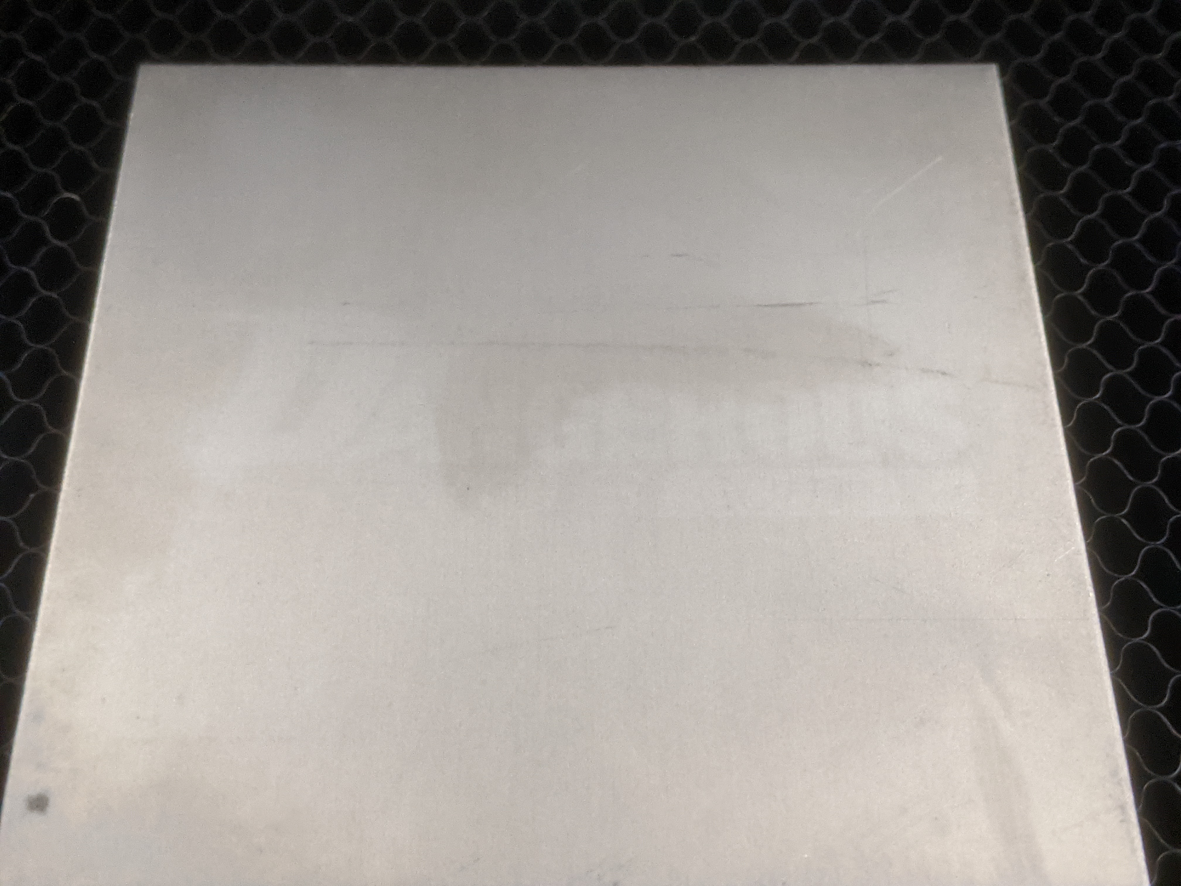
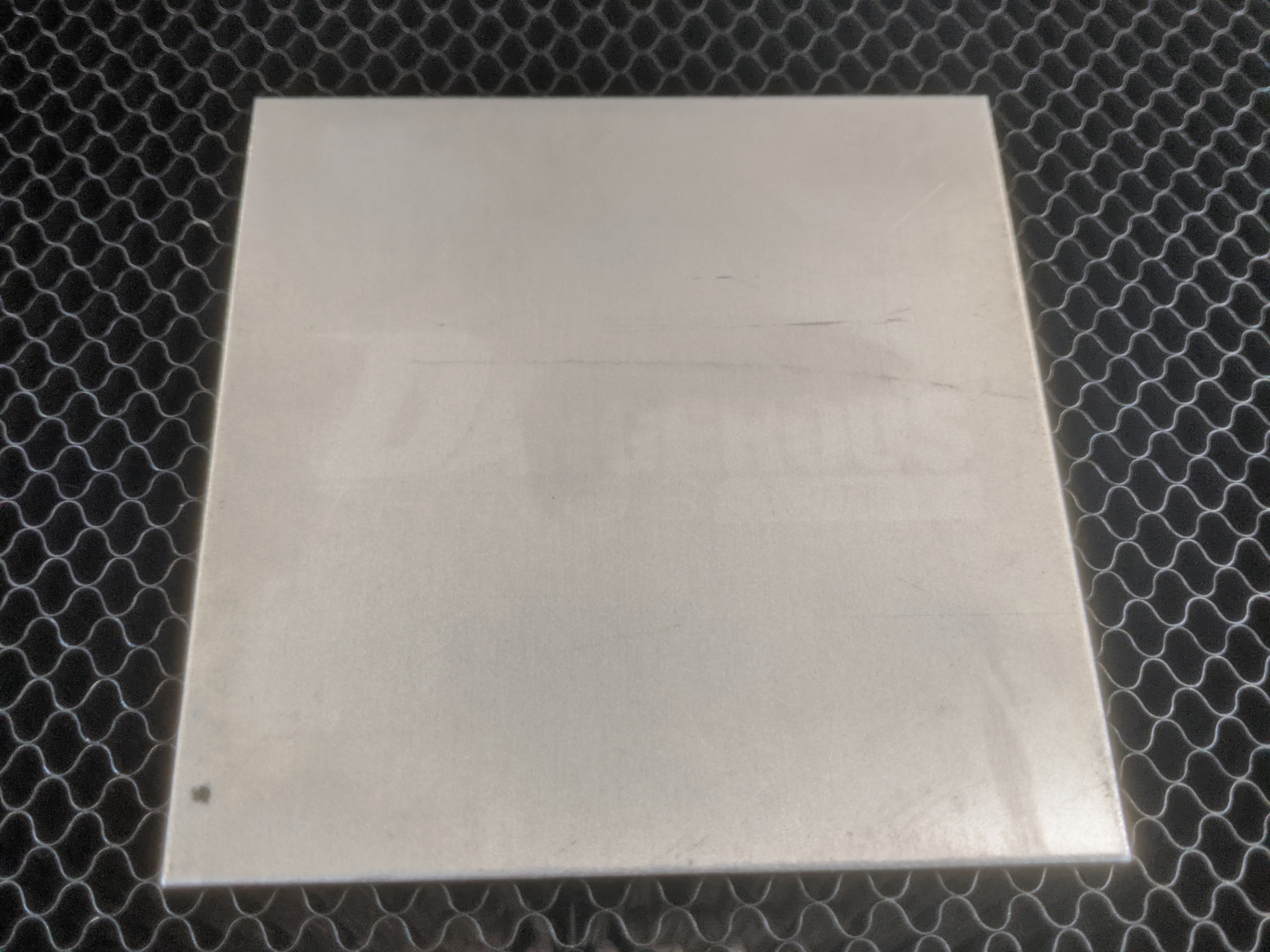
After some failed attempts with real material, Glowforge support (who have been excellent btw) instructed me to run through a beta calibration procedure (they also use Discourse!) which etches out a pattern of Glowforge logos on a piece of high contrast new material. Then the system attempts to calibrate the camera based on this pattern.
Testing calibration
After doing such a procedure I hoped it would be “problem solved”, but alas no the same issue persisted.
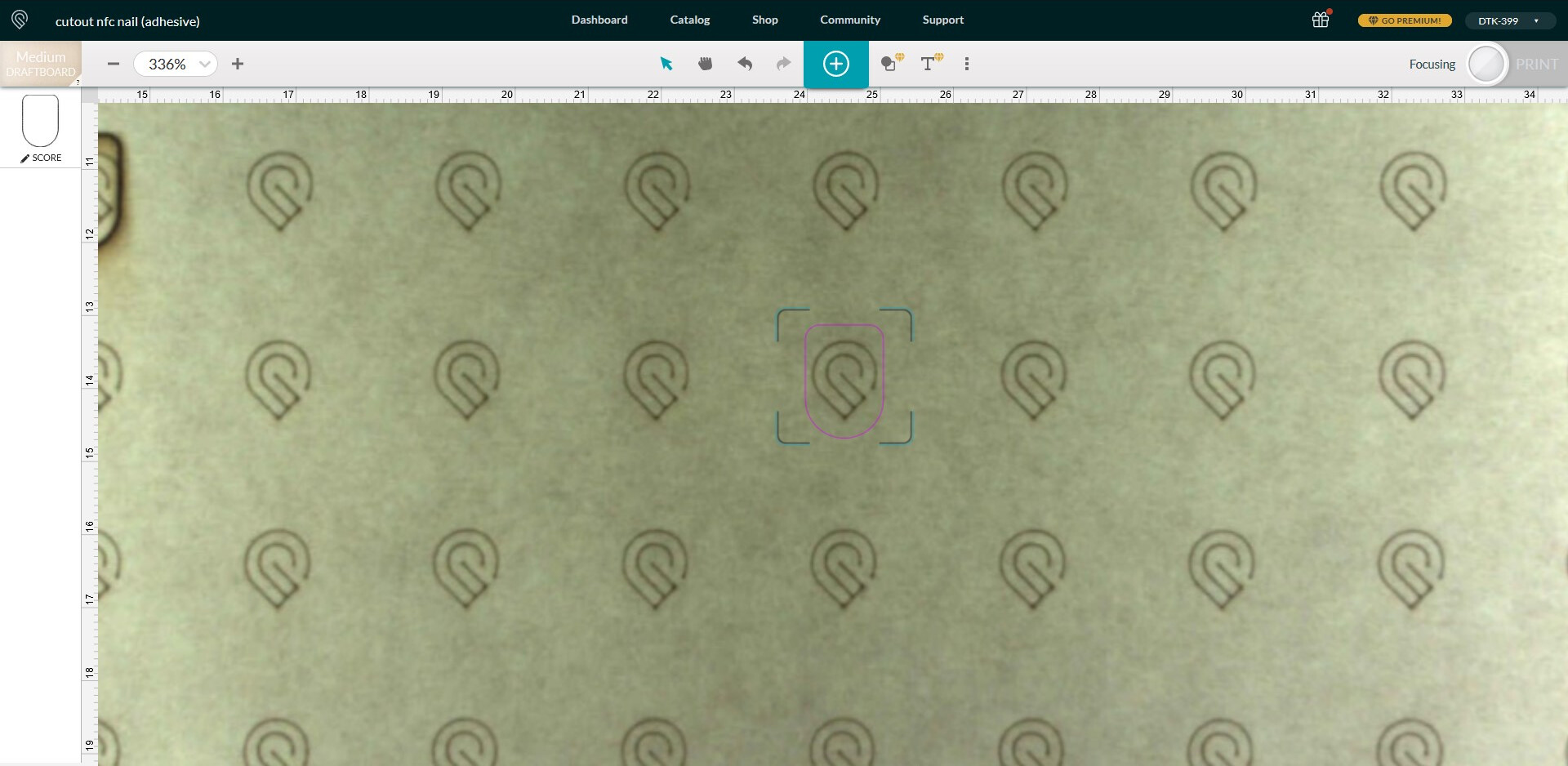
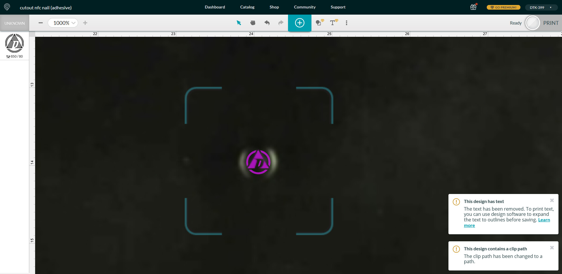
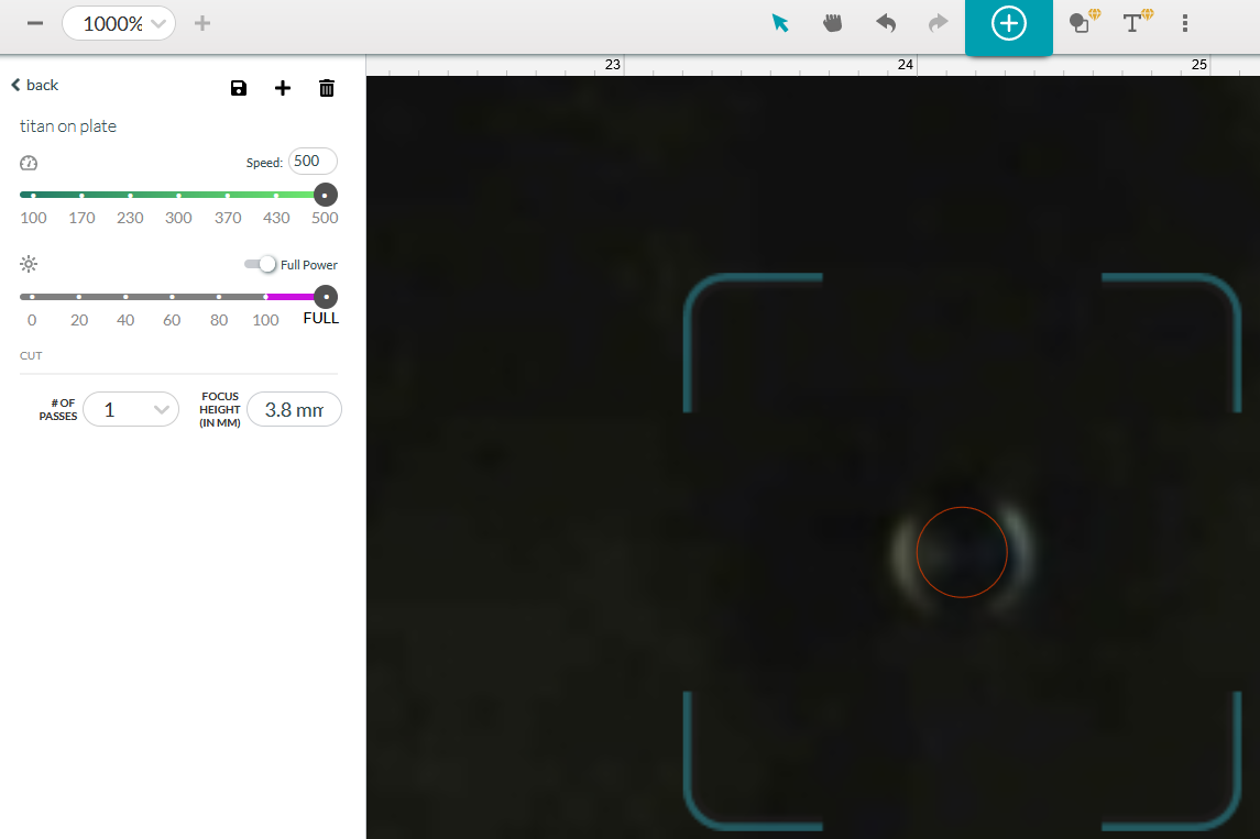
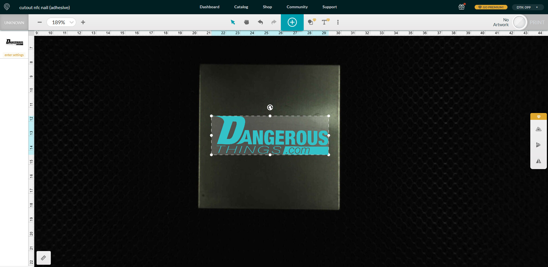
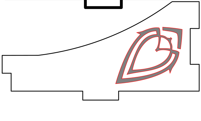
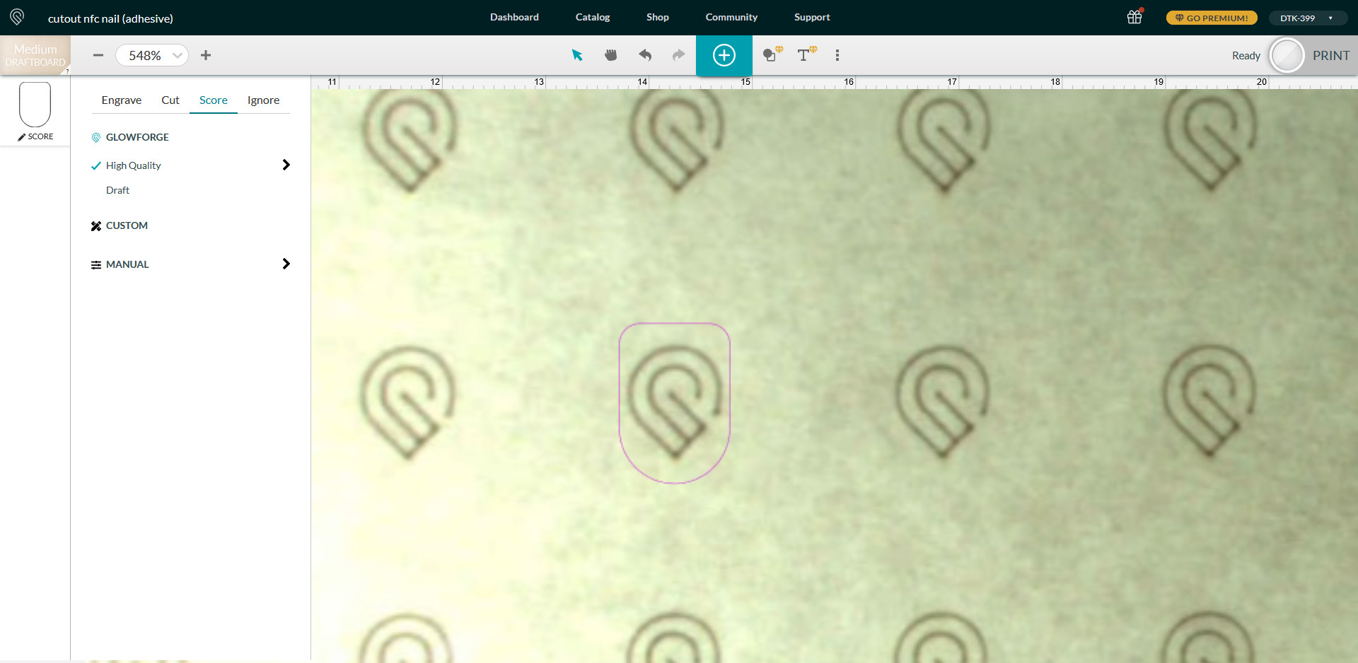
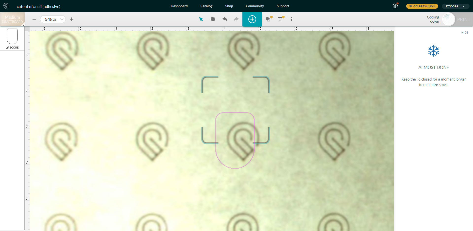
Positioning the pattern over the target
I simply placed a pattern over one of the logos and proceeded to print.
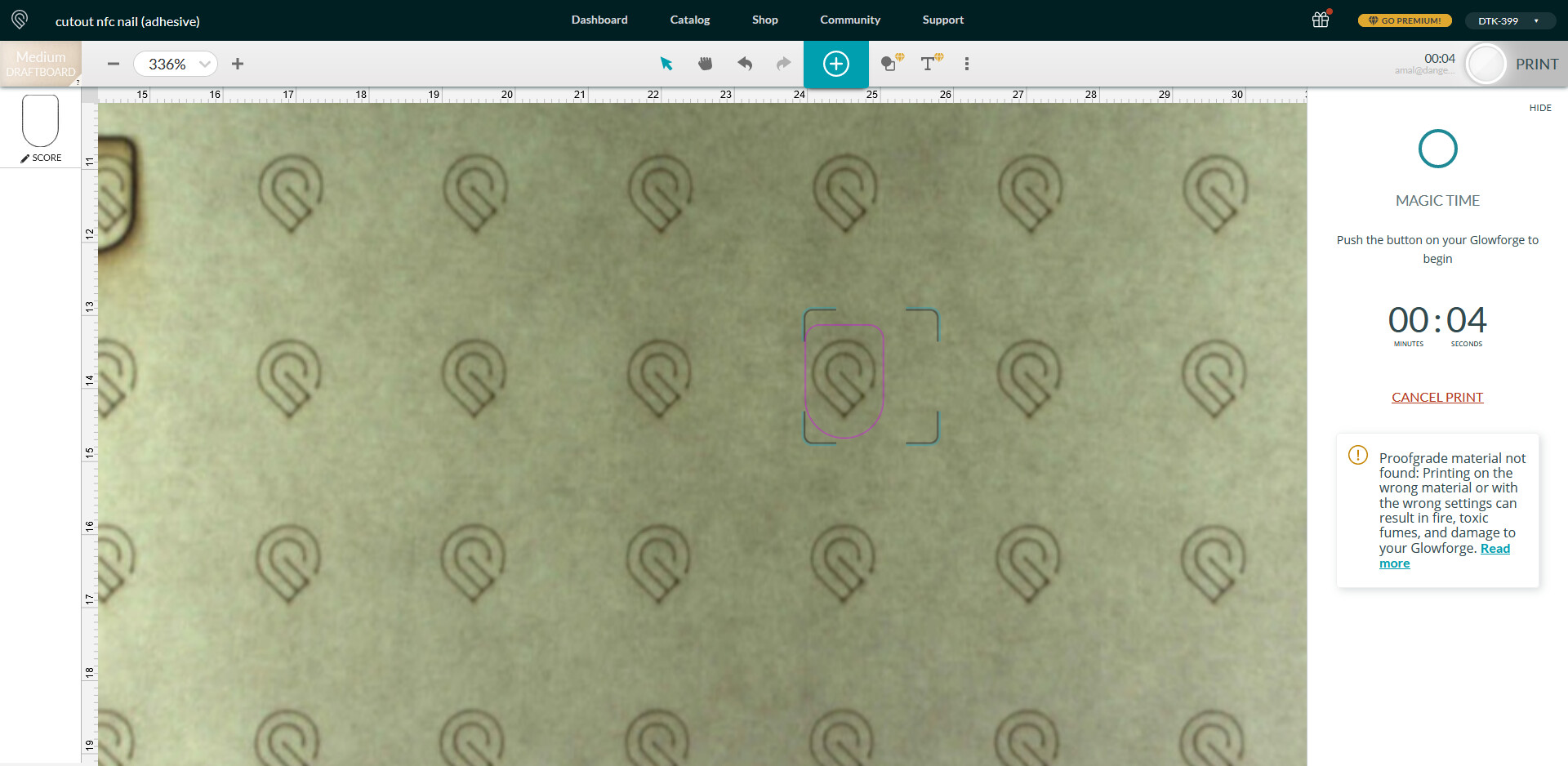
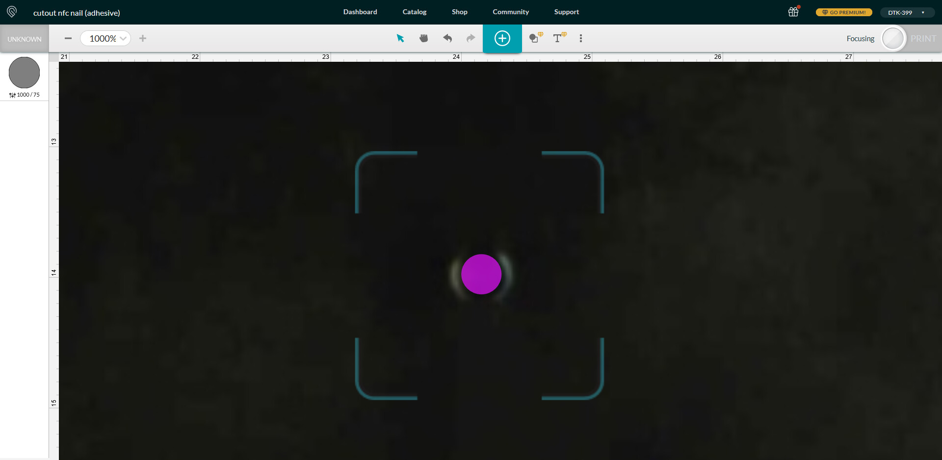
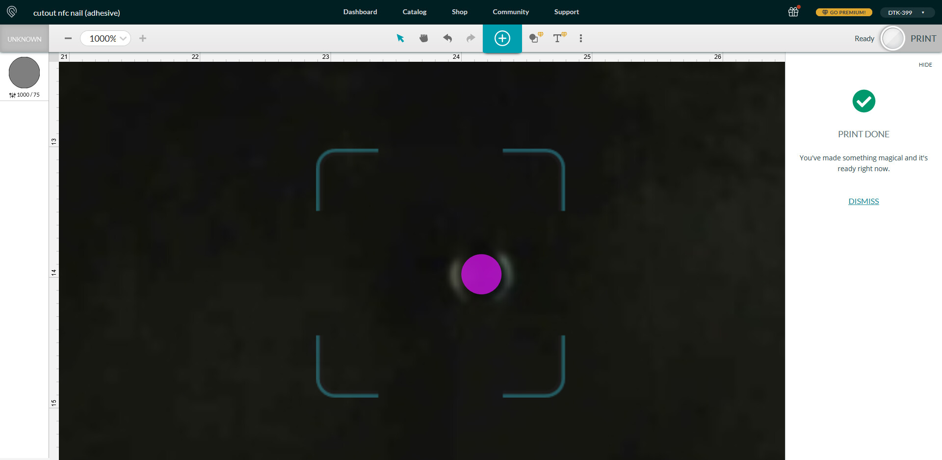
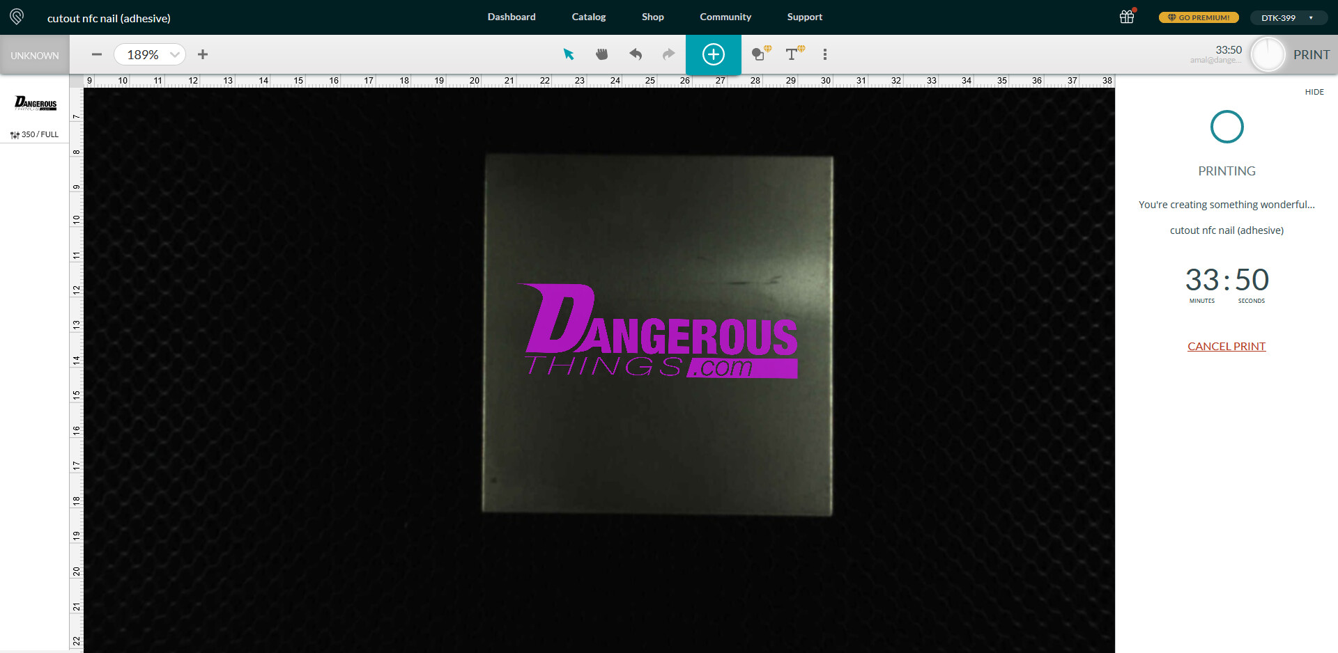
Printing…
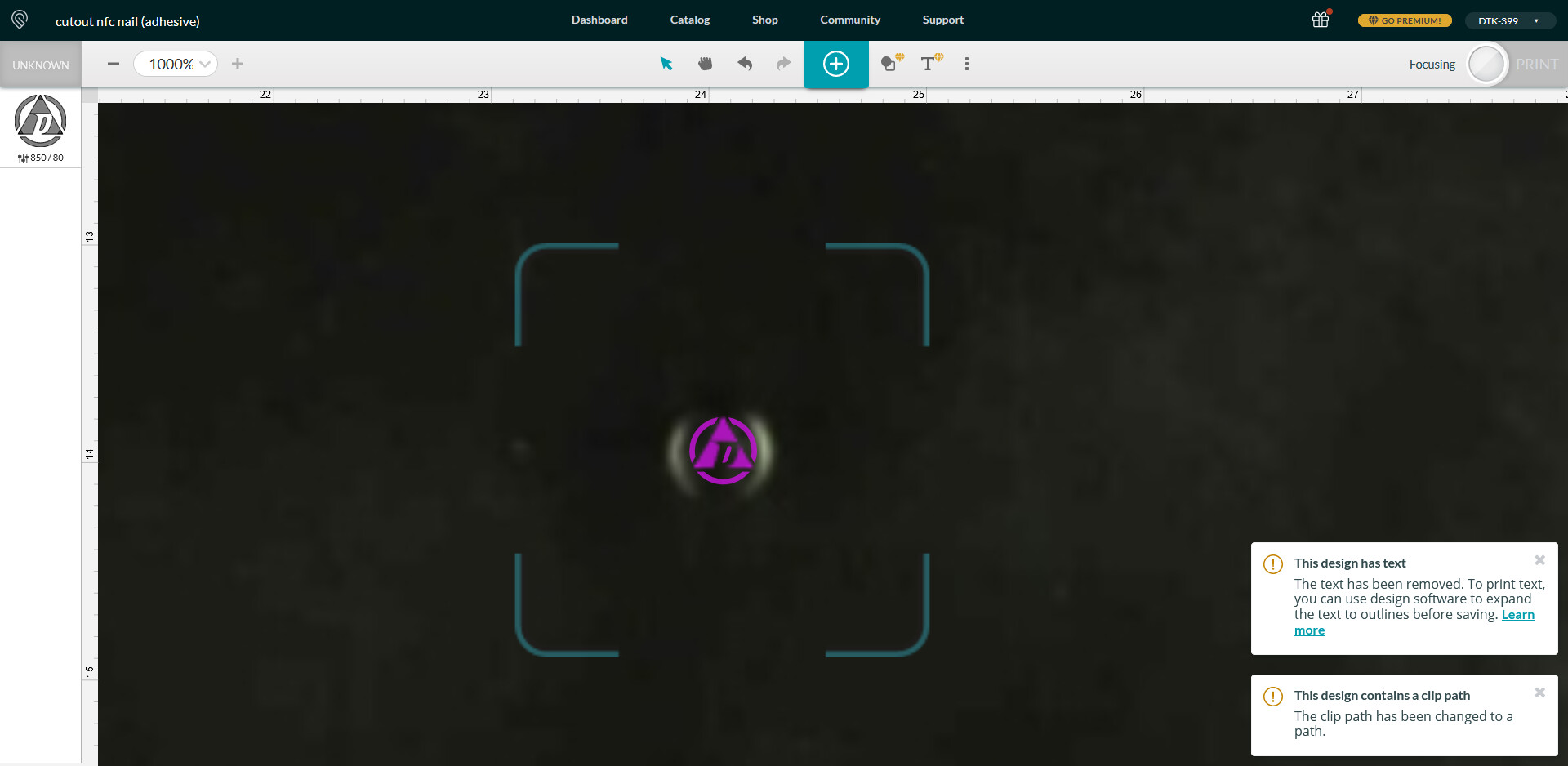
As you can see, it did not turn out well..
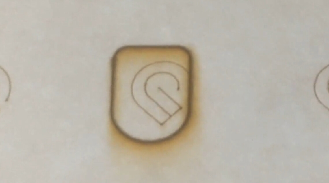
Some hope
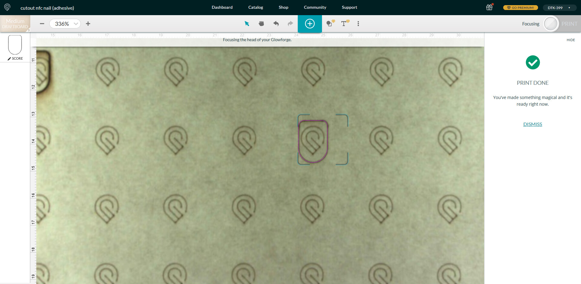
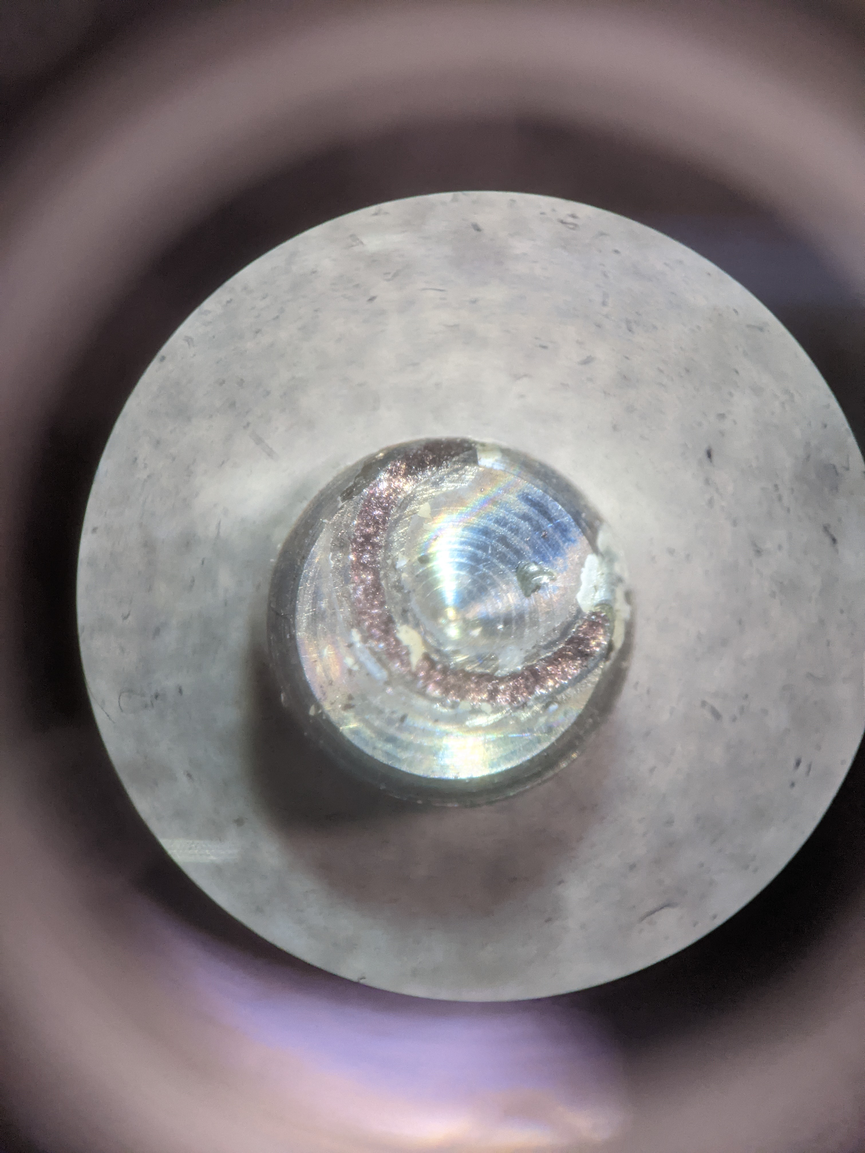
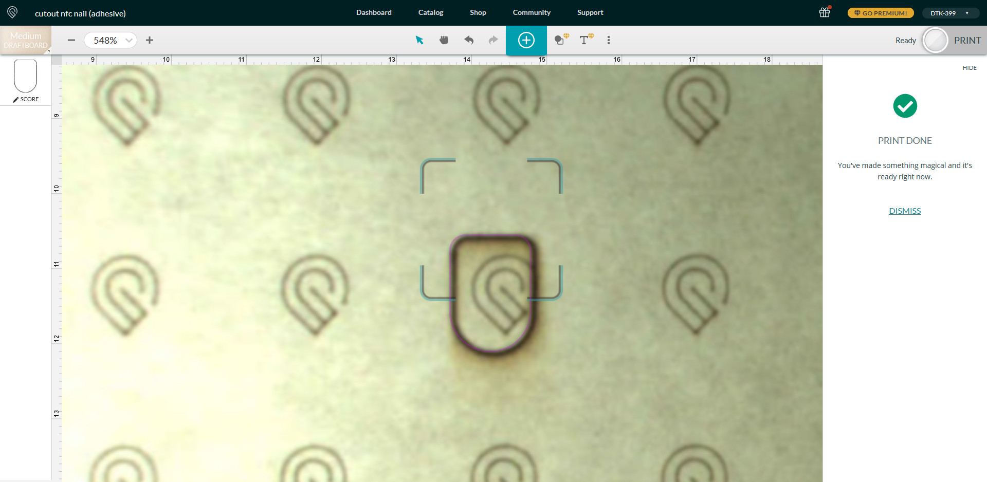
There may be some hope yet for Glowforge though. You can see as the print process started, the bed camera image jumped over. It jumped over quite a lot, actually placing the pattern such that the laser would be cutting right through the right side of the logo.
After the print, the bed camera jumped back to the right slightly, showing the actual print aligned with the pattern just on the edge of the logo. I have no idea if this is some kind of image automated image alignment with the score marking on the target, or if deep inside the bed camera system there remains some bugs to be quashed. If it’s the latter, then it appears that camera accuracy is possible.. but that accuracy is not being represented throughout each step of the design process from layout to print to post-print.
Returning the Glowforge
In the end, I can’t wait for these bugs to be sorted out. I am returning the Glowforge and will be exploring other options.