THIS IS A @Vicarious PROJECT
Direct copy from the Dangerous minds podcast webpage.
I thought this would be a good place to share it on his behalf. (with permission)
xNT NFC Computer Unlocker by Vicarious for DM-U
Posted on October 24, 2016 by c00p3r
xNT Tutorial : NFC computer unlocker
After finishing this project, you no longer have to worry about criminals who like shoulder surfing,
people who look over your shoulder while you enter your password.
Hardware parts needed:
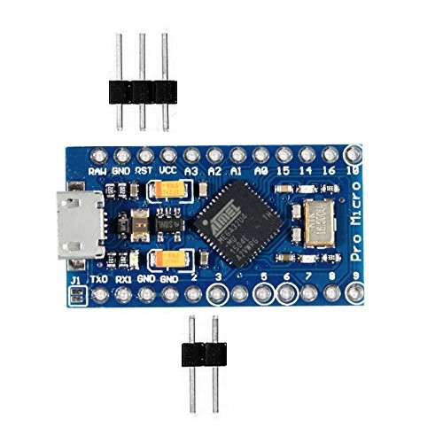
• Arduino Leonardo Pro Micro (regular Leonardo also works but I’ve chosen the Leonardo
Pro Micro because of it’s small form factor)
• Computer
• Micro USB cable
• PN532 NFC R/W module
• Soldering iron and soldering materials
• Wires, wire cutter, wire stripper
• xNT RFID/NFC tag implant
Optional:
• Heat shrink tubes
• Male and female headers
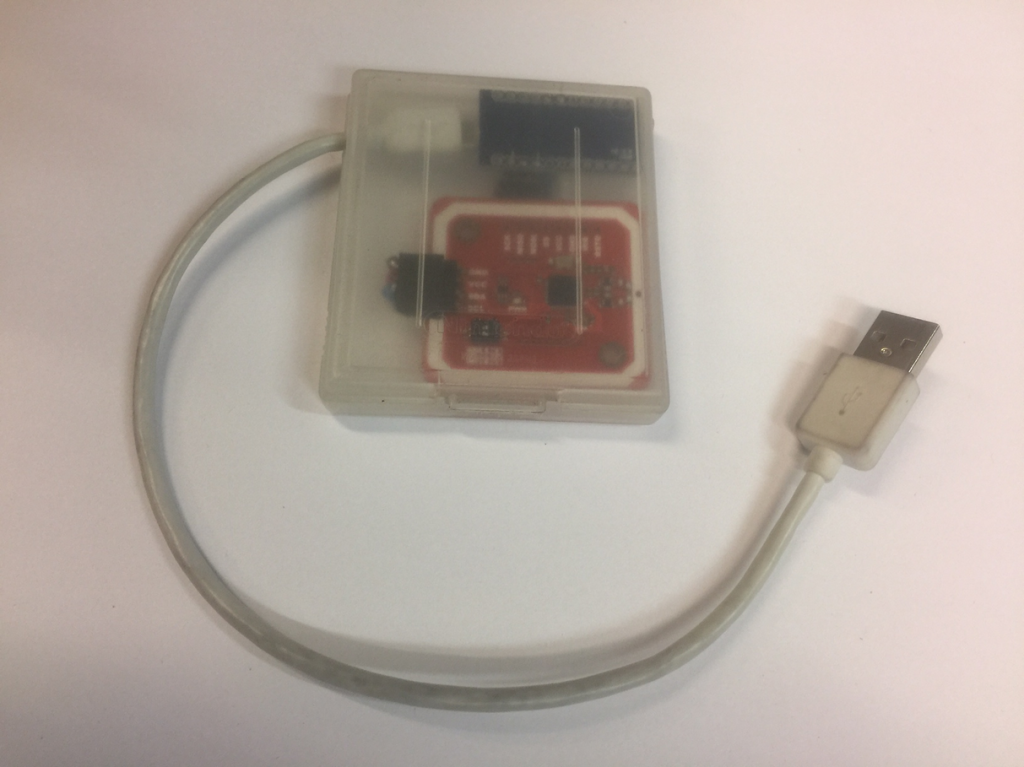
• Plastic enclosure to keep the hardware in (I used a Gameboy cartridge case)
• More NFC tags
Hardware preparation:
- On the Arduino Leonardo Pro Micro, solder male headers on GND, VCC, digital pins 2 & 3.
For more stability I also soldered the male header pin in between on RST. - To make it fit in the Gameboy cartridge case, I bent
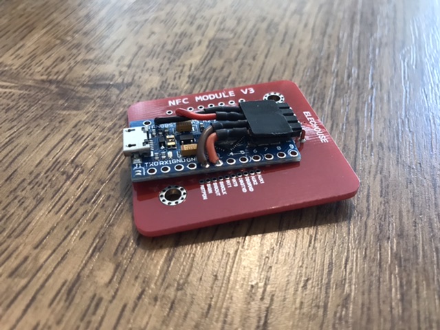
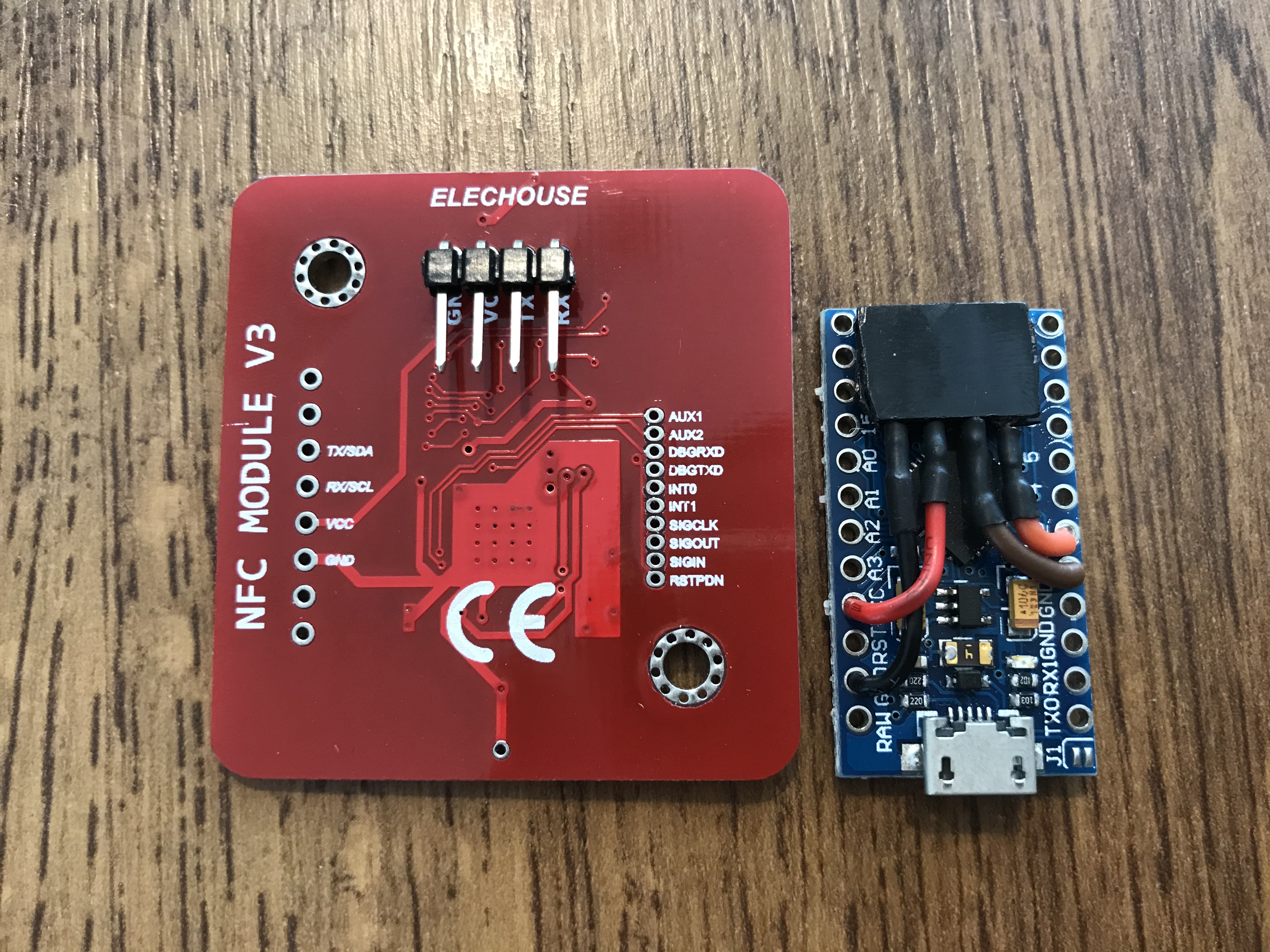
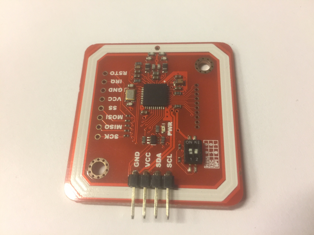
the male header pins 90 degrees. - On the PN532 NFC R/W module, solder male
headers on the I2C connectors. The PN532 module
should come bundled with male headers for this
purpose. - Set the DIP switches on the PN532 module to I2C
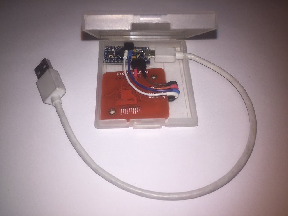
mode. 1: on, 2: off - Attach the female headers on the male headers. Place
the Arduino and the PN532 inside a plastic case, I
used a Gameboy cartridge case for this project and
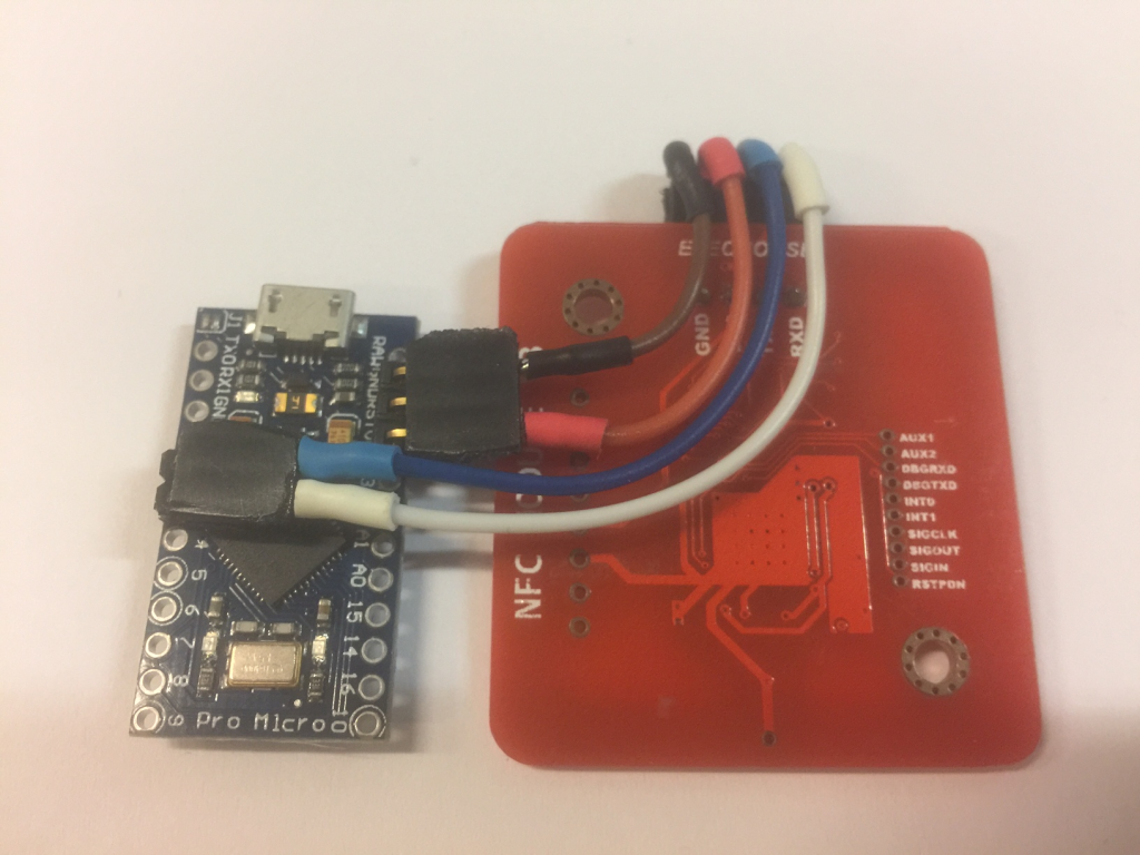
made a small hole for the micro USB cable. - Cut 4 wires to the right lengths and solder them to the
female headers. Optionally add heat shrink tubes to the solder connections:
a) From Arduino GND to PN532 GND
b) From Arduino VCC to PN532 VCC
c) From Arduino digital pin 2 to PN532 SDA
d) From Arduino digital pin 3 to PN532 SCL - Attach the micro USB cable to the Arduino
Leonardo Pro Micro and your computer.

Software preparation:
- Download and install the Arduino IDE if you haven’t already.
- From within the Arduino IDE, download the PN532 library
- Go to GitHub - Vicarious84-zz/Arduino-Leonardo-NFC-Autotyper: Automatically send a string of characters as soon as an RFID/NFC tag is scanned. and download the
Arduino sketch. Opening the .ino file should automatically load the sketch in the Arduino
IDE. - From the Arduino IDE menu, choose the Arduino Leonardo under “Tools” → “Board”.
Select the correct port under “Tools” → “Port” - Upload the sketch to the Arduino, either from the menubar (Sketch → Upload) or the
toolbar. If there have been no errors during upload, we are one step closer to finish the
project. - Open the Serial Monitor from the menubar (Tools → Serial Monitor) or the toolbar. In the
lower right corner of the Serial Monitor window, set the baud rate to “115200 baud”.
It should say “Scan a NFC tag” every 30 seconds. - Hold an NFC tag such as the xNT RFID/NFC tag implant near the PN532 module and watch
the Serial Monitor window for a 7 byte string containing the UID in hexadecimal characters
(0-9, A-F). Mifare Classic tags have a 4 byte UID. - Copy the UID string from the Serial Monitor window and paste it in the Arduino sketch,
replacing the example UID string of “01 23 45 67” (4 byte UID) and/or “01 23 45 67 89 AB
CD” (7 byte UID). - Replace the texts “Hello, World!” and “Passphrase” with the text you want automatically
sent to the computer. - Save the edited sketch and repeat step 5 to upload the edited sketch to the Arduino
Leonardo. - Close the Arduino IDE application. Log off or lock your computer. Make sure the cursor is
in the password edit box, then scan the xNT tag implant.
If everything worked correctly, your passphrase should automatically be sent to the
computer!