Then my interest in implants grew. I purchased the xEM specifically so I could use it with the punchclock… But after some thought (and before implanting it), I decided an xNT would offer more options. But that gave me the challenge to convert the punchclock to NFC.
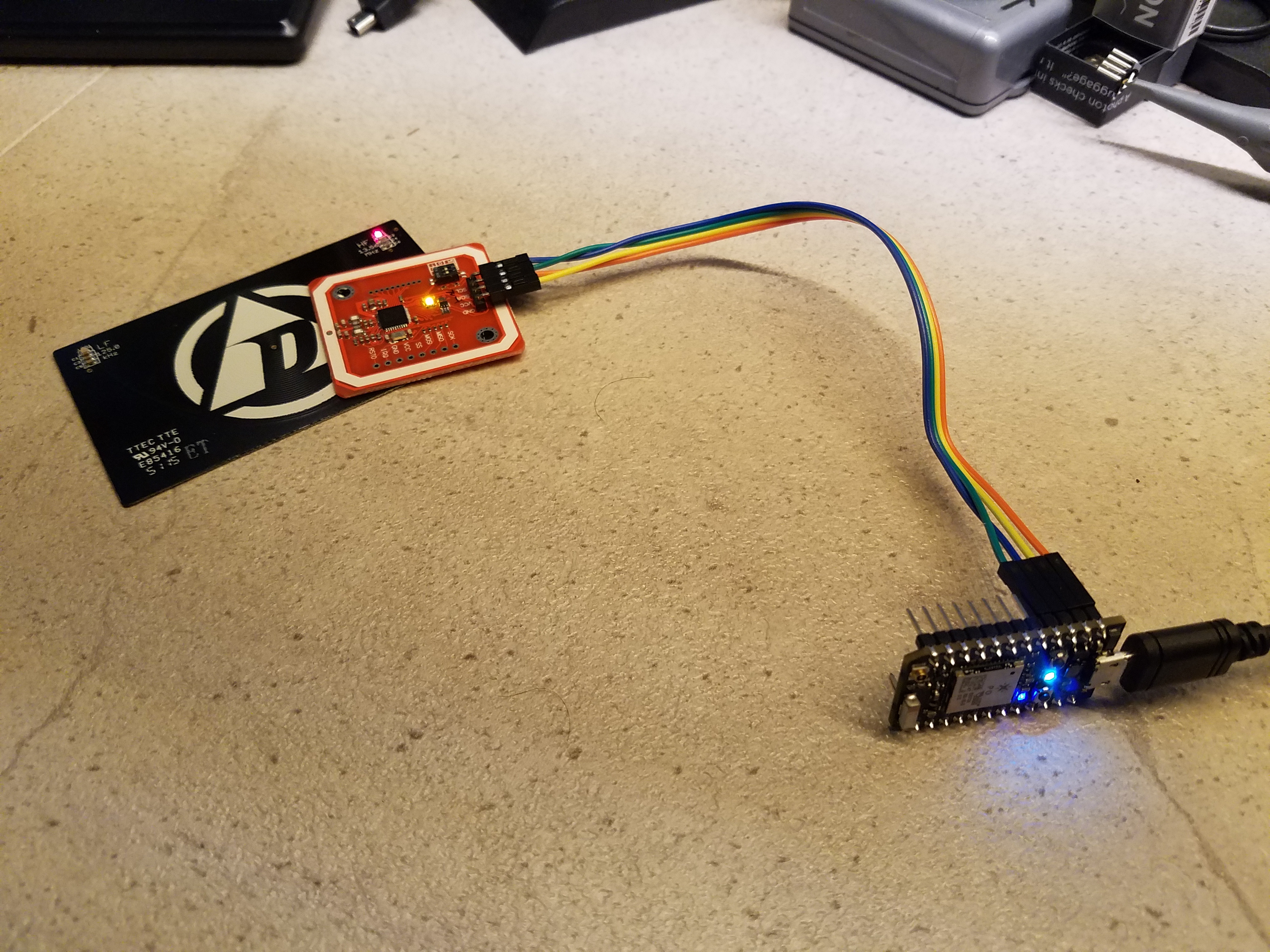
I purchased a PN532 thinking it would be much like the ID-12LA module that Sparkfun sells where you just apply power and when a card is near, it spits out the ID. Boy was I wrong.
After a lot of hair pulling, and some help from equally perplexed people that posted solutions on the web, I was able to get it to work.
I had two major issues…
First issue was I could not get reliable communications. I could get a reply here or there, but not consistently. I then found this post that outlined very specific (and undocumented) timing requirements when using the UART. http://www.avrfreaks.net/comment/2115266#comment-2115266
After adhering to these requirements, communications was 100%.
After that, everything was working fine, except the cards just wouldn’t read. Communications was working, I could see the RF field being polled, but it just wouldn’t read. It would come back and say zero cards found. I have several cards and none worked. I was certain there was something wrong with the module… I then found this post that said try the RF test. Sure enough, I tried the test and then tried to poll for cards again and it worked right away. I don’t know if this is a bug or there is some setting that the RFTest sets that I’m not setting, but as it stands, I have to run the test each time it’s booted to get cards to read.
During this adventure, the DT diagnostic card was instrumental during troubleshooting. (Though at one point I did connect my spectrum analyzer…)
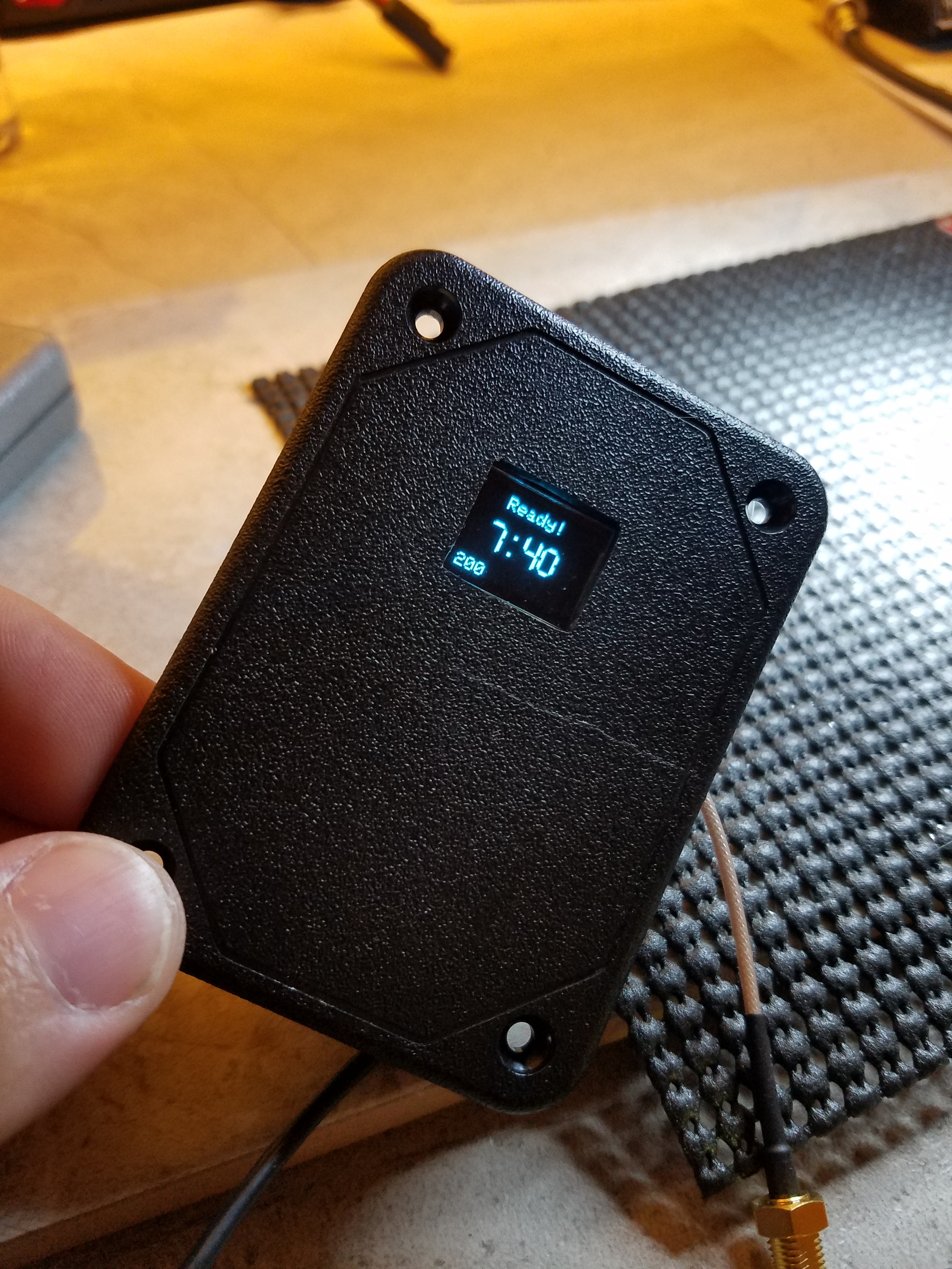
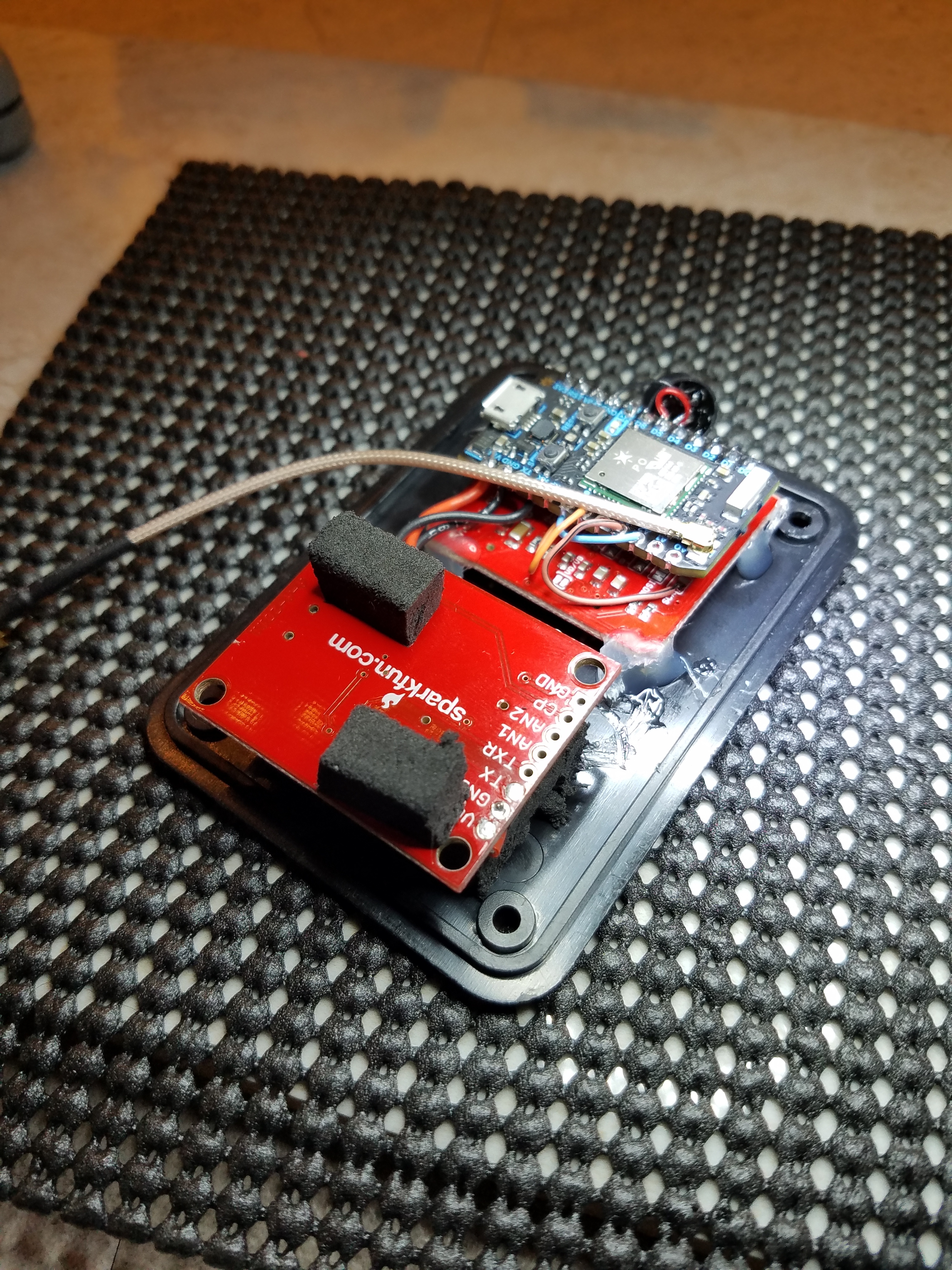
So I’ve finished this project, squeezed the PN532 into the box (almost didn’t fit) and it’s been working fine for over a week. I got a sticker tag inside my wallet that works great and awaiting my xNT install.
Today I held my Galaxy S7 up to it and to my surprise, the timeclock read it. As stupid as it sounds, I never considered the phone to be a tag, just a reader. So I was like “Oh nice, I don’t even need the tag in my wallet” and went to update the system with the tag that was reported when I scanned the phone.
I went to scan it again to test it and my system said it was still an unrecognized tag. I looked at the scan log and sure enough, the tag was different than what was scanned previously. I did a few more scans and found that a different ID is reported every time it’s read.
When I was writing the code, I tested with the three tags I had so I don’t know if this is a code problem or the phone is really reporting different IDs.
I don’t have another PN532 (have 2 more on order) so I can’t test yet…
Anyone have any thoughts?
I do have Samsung pay enabled… I wonder if that has something to do with it.
Well the PN532 antenna is certainly not optimal for x series tags. I think I read that here somewhere… I probably have some swelling but even mounted flat against the cover, it will not read through the plastic cover of the project box. Well it read like twice but I looked like someone dancing at an EDM concert trying all different orientations. And it was not repeatable. It does read if I basically put it right on the PCB.
Time to brush up on antenna design… lol.
Any pointers on antenna types that work best with these tags?
Cylindrical antennas work best, but they are bulky as hell. They also only really work well if you can place the length of the x-series tag parallel to the reader’s cylindrical antenna.
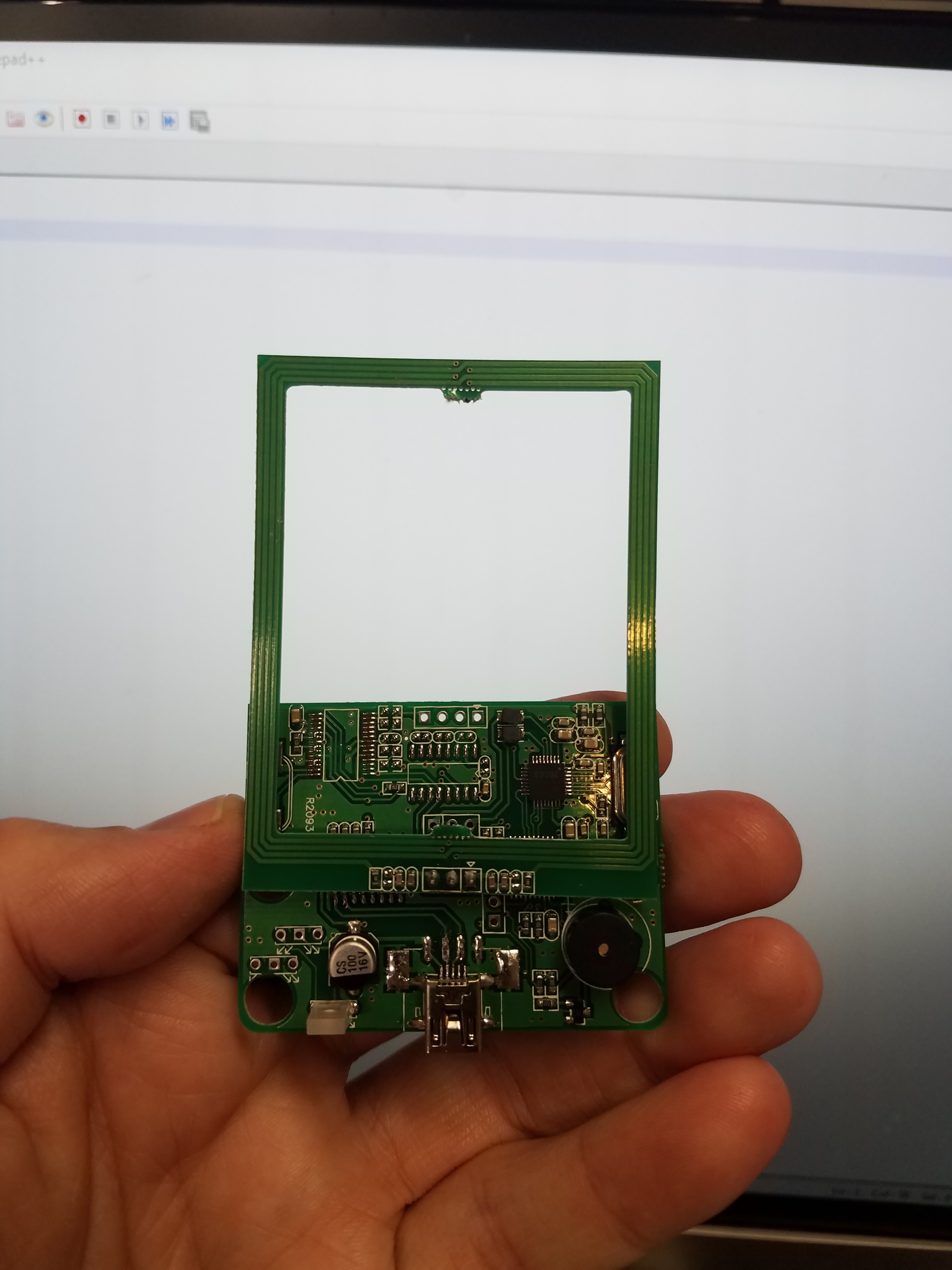
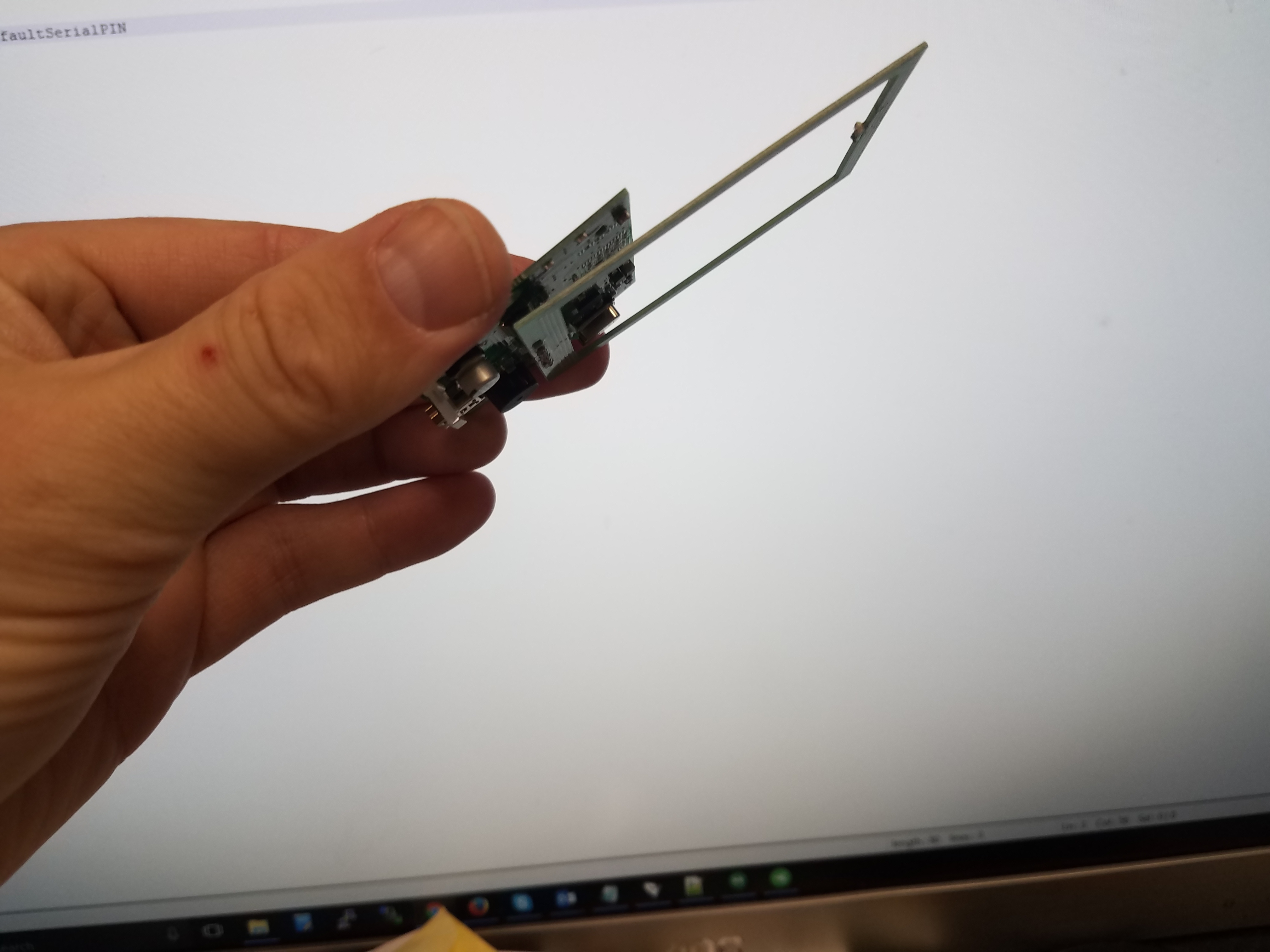
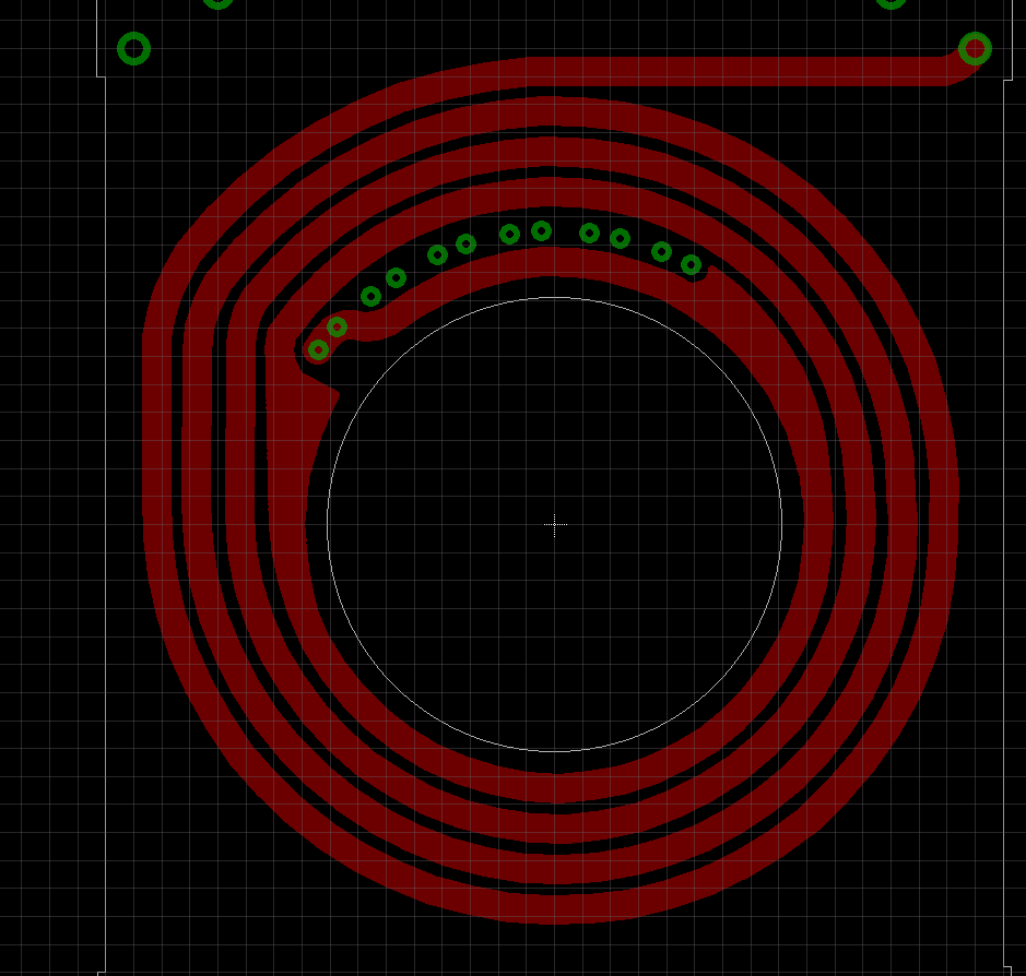
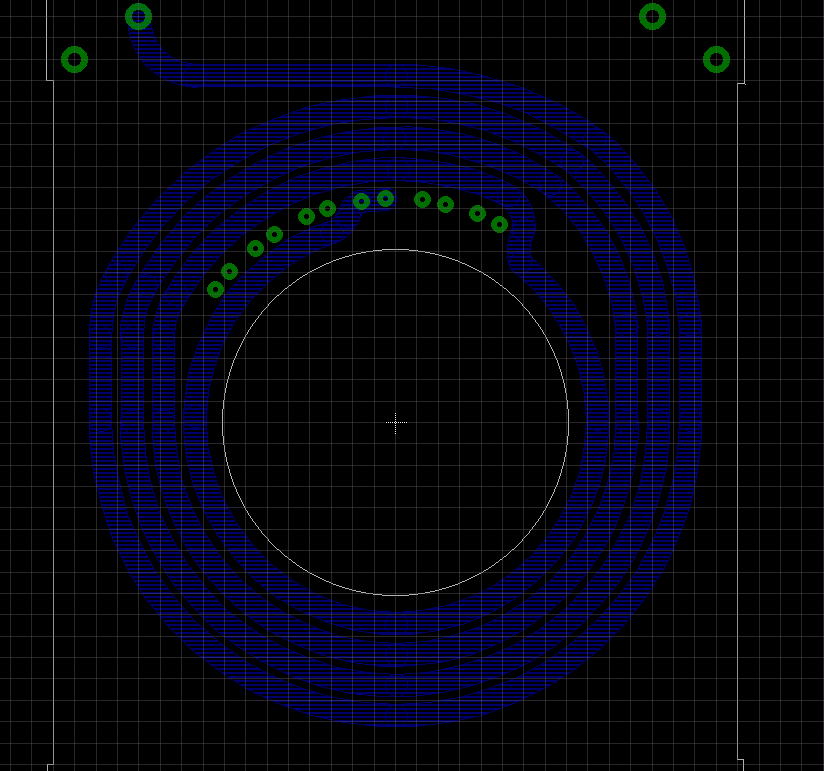
That said, I just got a reader that uses a printed PCB antenna and it gets decent range with the xNT… about 15mm off the PCB antenna… but they did some funky stuff to make that happen… the antenna PCB is hollow (almost no material) and floats in free space off the side of the logic board.
It would be interesting (though expensive) to see if something similar could be done as a tuned antenna…and if it would improve performance to give it a little more depth to the antenna…
So of the three PN532 boards I bought, two were from amazon, one was from ebay, but it was dropshipped from amazon.
I noticed in another thread that there was a difference in the silkscreen between the one DT sells and the ones I bought from amazon/ebay. The amazon/ebay ones were significantly cheaper than the DT one…and now I know why…
They appear to be fake.
The one DT sells has a significantly better range reading an implanted xNT than the amazon ones. The amazon one (all three amazon boards I bought), I basically have to have optimum orientation and touch my skin to the PCB for it to read. The DT one gets > 1cm read distance with my implant. Using the xLED, the DT one seems to put out a little more power.
The amazon one had an amber power LED, the DT one has a red one.
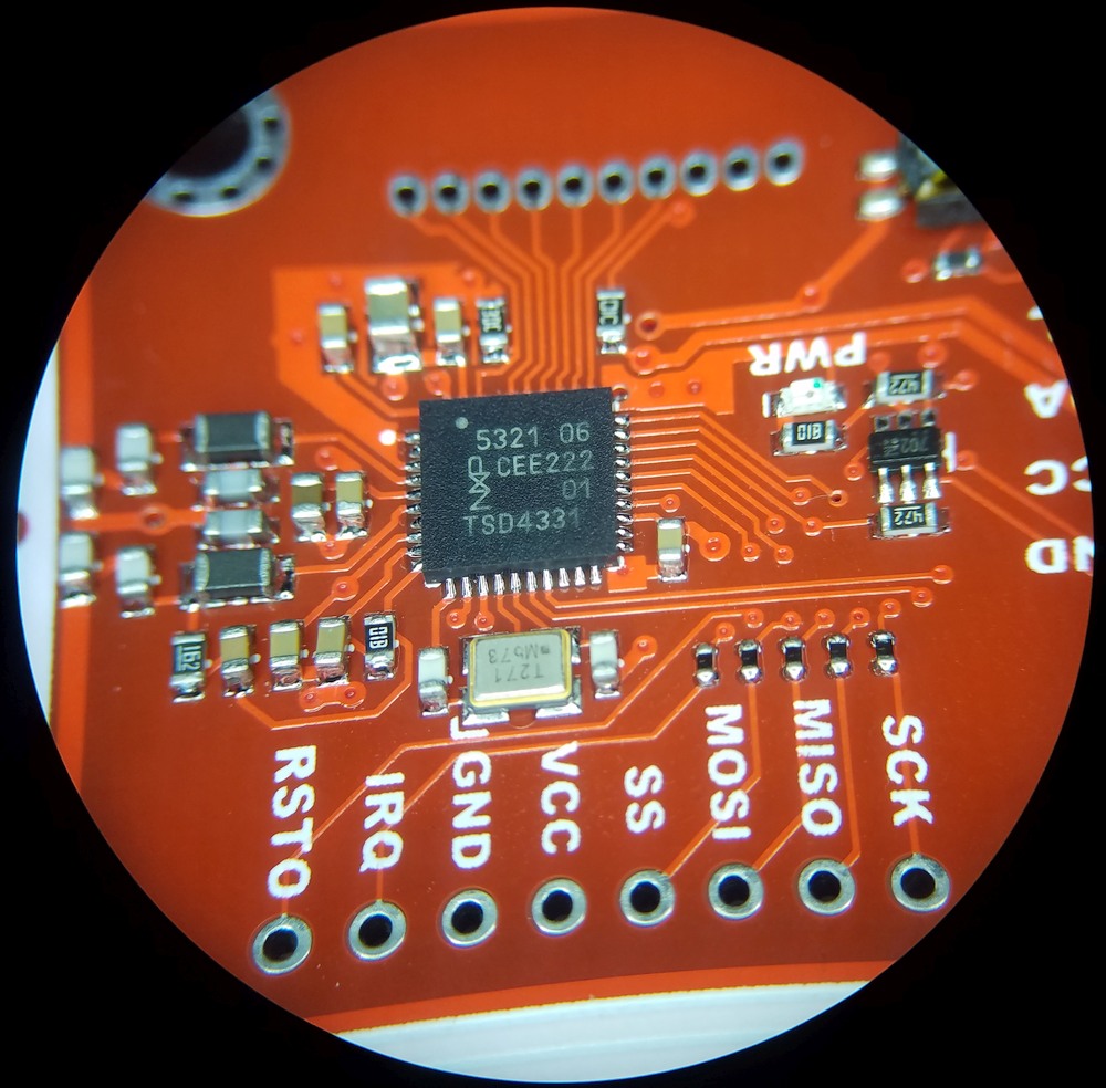
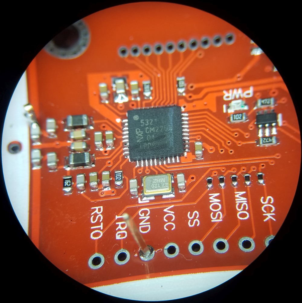
I see some minor differences in the PCB layout that tells me it’s not from the same file… but I think the biggest “issue” is these chips are not real NXP chips. The logo isn’t quite right on the amazon version.
Looking forward to swapping out the fake PN532 in my punchclock for the DT board so I can finally use my implant for something other than grossing my friends out. haha.
My 2 star review on amazon caused the seller HiLetgo to send me this:
I realized you said the this RFID Module is knockoff and have significantly less range than real ones. Yes, it's exactly same as you said, this product was made in China with cheap cost, that's why the price of it can be so low, but generally it can meet some simple demands like reading large format tags etc as you said. Anyway, they works, so if they are useful at your side, we would like to refund you $5 for each, total $10 for two as the compensation for the inconvenience on this issue. Or would you like a full refund with a return to Amazon, we are very sorry for the inconvenience caused for you, and please kindly let me know which one you like? So we can resolve your problem as soon as possible.
I’m impressed they even cared nevermind admitted they are fakes.
hah wow! the only other time i’ve seen this is when i called a vendor in new york about his shitty service and absolute refusal to work with customers… i asked “why does every person i buy from in new york hate customers?” and he said “because this city is like a boat overloaded with rats… if you don’t buy the guy behind you will pay double just to get you out of his way” and i was like “holy shit”.
As a former NYer, I completely agree and is one of the reasons I left. NEVER buy from any company located in Brooklyn, Queens, or Manhattan. Most of them are scammers anyway. The majority of people there are just awful narcissistic self entitled a-holes than care more about the tissues they blow their nose with than another human being. No offense if anyone here is from NY… lol.
@ckonkol
I’m working with the PN532 board now. It can be pretty difficult to get working. Here are the GitHub pages for the three libraries you need:
elechouse PN532 library:
NDEF library:
For the elechouse library, it actually comes with 6 distinct libraries. I only used “PN532” and “PN532_I2C”. The NDEF library included with the elechouse package is necessary, but wasn’t working for me. I went to get the more up-to-date version from that second link.
To get started, I recommend you check out the example sketch “iso14443a_uid.ino”. I’ll attach it to this post so there’s no confusion.
Another note I learned at great cost while troubleshooting this thing. EVERY TIME you load a new sketch, cycle power to the PN532 module and THEN open the serial monitor. You really only need to do this while you’re rapid-fire loading sketches to troubleshoot, but it can be endlessly frustrating if you don’t realize it and you’re just sitting around waiting for a soft-bricked module to do the thing. iso14443a_uid.zip (1.5 KB)
I use PN532 for most my projects, and the elechouse library (with some modifications for low power mode).
Here’s one version that I use to start the snowmobile with.
Heavily dependant on the tag antenna. You might get 7cm read range with a flex tag in open air, but have to physically come into contact with the board when trying to read an xNT in the glass capsule. Objects in the vicinity can also attenuate some of the field and reduce read range.