That looks… crowded.
this
or that

because the flexMT (flex Mifare T5577) is a much smaller diameter than the flexNExT … 33mm instead of 41mm.
2 Likes
I need a flexMT
3 Likes
Starting to sound like Pokemon. Oh look, it just mutated into something newer and cooler!
2 Likes
After rethinking it, it probably isn’t the best idea to put on the back hand… I am not really sure
A lot of veins and tendons for quite a large surface area device to cover.
I would be looking probably above the wrist.
A little less delicate organic structures to get in the way, but still practical for readers.
Considering it’s pretty flexy though, in comparison to the pressure that silicone subdermal implants would impose I would think it’d be OK?
Tough to say… everyone’s hands are different.
Also. iPhones work pretty well too…
3 Likes
Do the lights flash to represent specific functions or read frequencies?
No, the phone sends out pulses of power to see if there is a tag it can read. I think it is a power saving feature. The lights will be solid with a USB reader or the phone once it detects the chip.
Then why the flash of one light between the big flashes of three lights?
I think it would be cooler, and more useful, to have the lights represent something. On the topic of the flexnext, a light assigned to each tag frequency would be a starting idea.
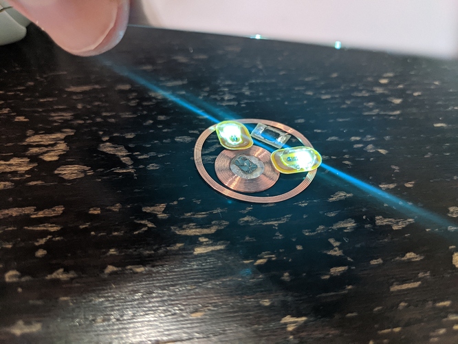
an oddity of the field strength… phones do some strange things with field power… and I think it was a combination of me slightly moving the phone and a lower power pulse that only manged to illuminate the LED closest or rather in the best position to couple well with the phone. In total there are 4 separate 13.56MHz devices (and one 125kHz device) in this implant… the NTAG216 and each LED all have their own antennas which are positioned in an overlapping fashion to maximize coupling for every device, however there are various “event horizons” that come into play when tinkering with magnetic fields. In short, it was a fluke.
There are no LF products like the NFC fingernail that I am aware of. LF antennas are able to just be printed like the HF ones afaik. It is why the flexEM is so chonky I believe.
Gotcha. Well, now I’ve planted the idea. Lights for function indicators! ![]()
It just keeps looking better by the day!
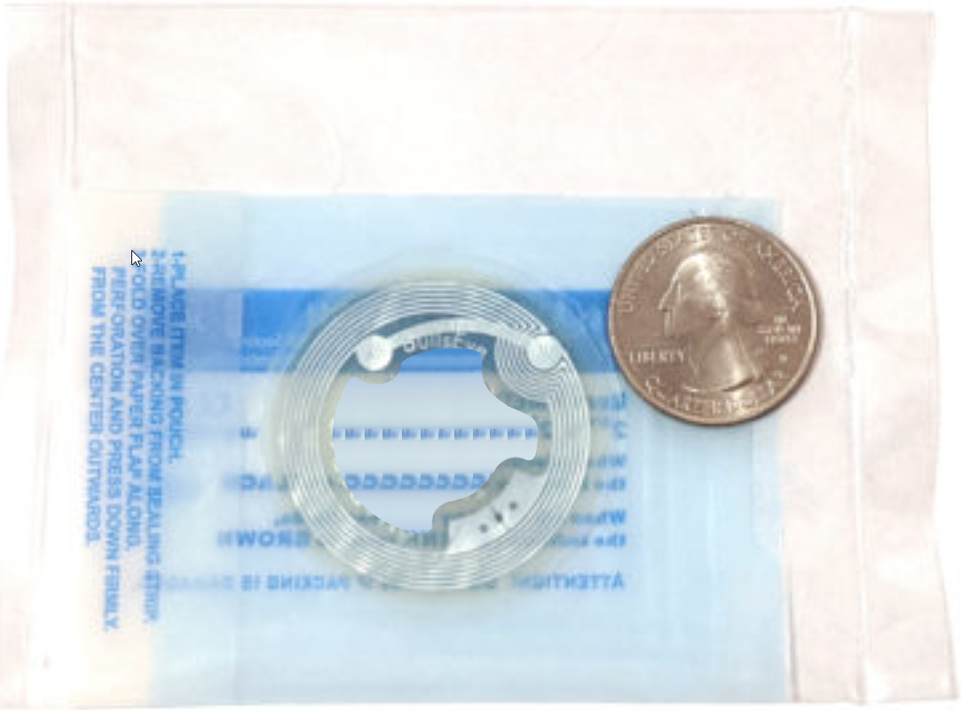
Amal, any chance of getting a FlexNext without the EM tag, and with a cutout in the middle? Or said another way, just the aluminum foil tag encased in biopolymer. Something like this:
The only body artist willing to undertake such an implant is coming to my town in 2 months from 400 mi away, and I’d like to use the opportunity of his visit to implant that thing. But I value flexibility and minimizing the area of detached skin more than I care for blinkies or dual-frequency.
Or possibly that thing with one blinky over the chip itself to protect it, is there’s added value.
1 Like
yeah i could do this… order a custom mod version of flexnext and i’ll one-off something for you… but after all the messing around with following the shapes etc i think the best approach for me to do this is to simply cut a single circle out of the center… i was able to make a little “map” of the interior, but then my expectation of simply being able to reduce size to cut the biopoly in the same shape was a bit dashed… angles didn’t line up and so it was a serious pain to try to re-map the smaller cut lines… so anyway… how about a 15mm diameter slightly offset circle cutout?
actually in testing the metal foil of the antenna where the chip is severely reduces performance of the LED to the point of it being basically pointless. I chose specific spots on the antenna trace to fit the 3 point LED pattern to avoid these issues. do you want me to put LEDs or no? Without them, I think this will be a very flexible implant since there will be no rigid structures inside and a nice big hole in the middle.
also, while working on flexnext inventory, i managed to pop out a few of these little things… just the nfc nail led only (in biopoly).
Because @Pilgrimsmaster asked in another thread, i’ll repost here;
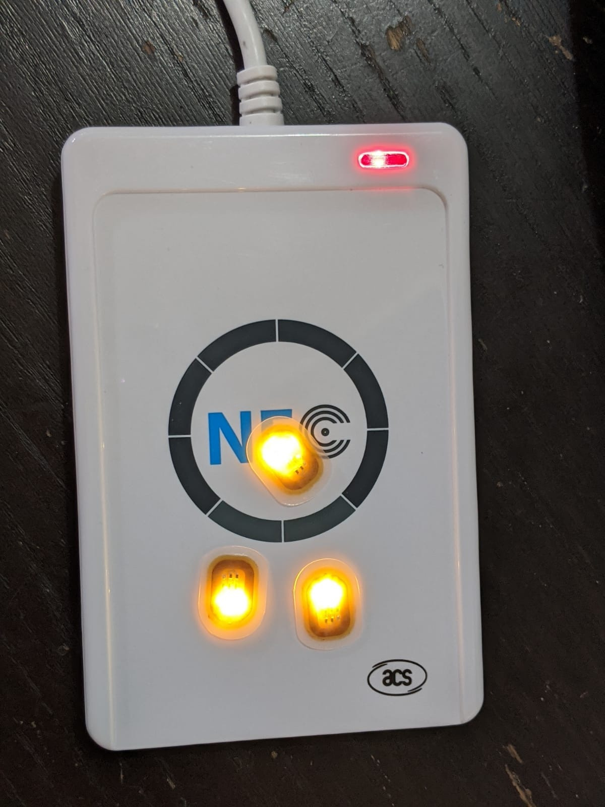
It’s very hard to give a straight answer with range comparisons because the xLED has a fundamentally different antenna, so range will vary drastically depending on the reader you’re interacting with, as well as the normal orientation issues. For example, the ACR122U has a specific spot where xLEDs perform pretty well… but no such spot exists for basically any other readers or phones. The ACR122U has a very unique antenna design with ground planes built to constrain and shape the field… very strange, but effective. Take one apart and check the PCB, you’ll see what I mean.
Here’s my totally unfair and basically pointless comparison on the ACR122U;
xLED; 15mm
nfc nail; 30mm
nfc nail on flexnext; 55mm
These are the “light points” where the LED starts to light up, not max brightness… but it’s typically only a few less mm to achieve max brightness, depending on the LED characteristics involved.
2 Likes
Oh right okay. I thought that solid aluminum foil zone around the chip was functionally dead. Interesting…
Also, I didn’t realize you carefully chose the spots you put the blinkies at. On the photos, they look like they were thrown in there in a triangular pattern at random.
In that case, no blinkies then.
Let me guess: your largest punch is 15 mm in diameter? ![]()
More seriously, that sounds okay. That means the widest “free floating” skin bridge between the outside of the implant and the inside cutout would be 16 / 17mm at the offset point. It sure beats 41mm. Assuming the skin reattaches at the center of course…
Yes that’s the appeal. On the other hand, I’m a bit worried it will be too flexible for the 4 “solder” joints - 2 to connect the chip, and 2 for the aluminum foil “jumper”. I mean at the end of the day, them tags were designed to be rolled and unrolled once, manipulated a bit once, then stuck to a solid surface forever. If those joints flex constantly day in and day out, they might come undone in the long run. Hmm…
I must be the only idiot in town to pay more to get less ![]()
Okay, let me do some more photoshopping tomorrow to picture what I’m really looking at getting, and to trial-position a paper cutout here and there, to see where it will best implanted, then I’ll place my order.
One last question: do you think I could get it in Finland before Sept 5th? That’s the date the visiting body artist comes to town.
Thanks man!
kinda… the inlays use standard via tech used with flex pcbs, even those meant to flex and move. Also the NTAG216 chip (and most chips on printed wet inlays like this) are meant for “smart poster” applications, some of which to involve loose material that does bend. I might think the biggest concern would be if your flesh deformed significantly enough to surpass anything that these might be stuck to by design, and did so on a regular basis ![]() Anyway, my point was that there wouldn’t be these rigid bits inside so if your hand had a lot of curve to the back of it, or if you wanted to place this on say, the side of the arm where there is a lot more curve but not a lot of modulation, the device should conform to the curve much more readily than a flexNExT.
Anyway, my point was that there wouldn’t be these rigid bits inside so if your hand had a lot of curve to the back of it, or if you wanted to place this on say, the side of the arm where there is a lot more curve but not a lot of modulation, the device should conform to the curve much more readily than a flexNExT.
I can say I’ve mistreated these things quite a bit, and the only thing that seems to kill them is a direct hit on the tiny chip… dislodges it from the flip pads… but, once encapsulated in biopoly (and under your tissue), it will have more than a fighting chance at keeping alive long term. Of course, anything is possible, but I’d be surprised if it became an issue.
Yep, I’ll try to get it out to you 5-7 biz days after you order.