Like many on this forum, I really wanted to be able to start my car via my implants.
However, my car does not have a push button start. This makes things a bit tricky. Specifically, my car is a 2008 Pontiac Grand Prix.
I didn’t really like many of the solutions on the market for solving this. There are a few RFID push button start kits, but they’re like a black box with closed firmware, and I didn’t like how many features some of them were trying to pack in (aftermarket alarm, remote start, etc).
I decided to build my own board, to handle replacing my ignition switch. I had done a decent bit of work with microcontrollers, but I had never designed my own PCB, so this would be a bit of an undertaking.
In this write-up, I’m not really going to mention many vehicle specific portions, as anyone here is unlikely to have my exact model.
I’ll start with a video of it starting, since that’s all a lot of people will probably want to see. My camerawork is very shoddy, and without the front panel finished. I realized after watching it that I had already authenticated on my last filming attempt, so the scan here is useless, but ![]() I didn’t feel like recording again, and my phone was almost dead. Just trust me, authentication works, you can see it light up my xSIID.
I didn’t feel like recording again, and my phone was almost dead. Just trust me, authentication works, you can see it light up my xSIID.
New video:
Figuring out the original switch's operation
So, the first step is obviously figuring out how the original switch works. You can’t replace it if you don’t know it. I could find very little information on the wiring of the ignition switch for my model. No diagrams, nothing. A few came up on google, but they didn’t make sense for my switch type, and I think they’re all for an older model. This meant I needed to work backwards and figure out how the switch worked myself. I didn’t feel like potentially breaking my only car, so I decided to go to the junkyard, and rip out an ignition switch to play with.
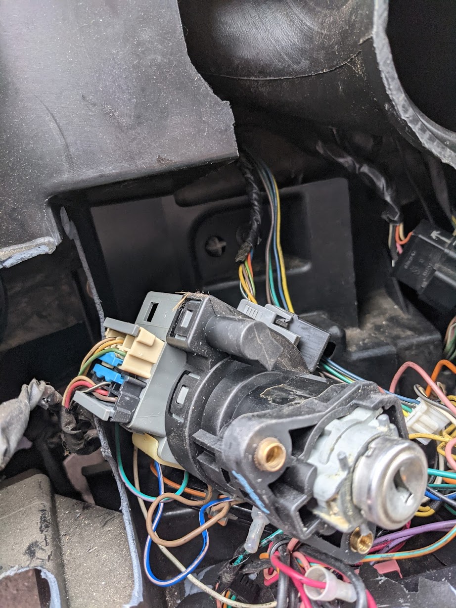
Getting it out was tricky, as on most cars, you need to remove the key cylinder by putting in the real key, turning it to ACC or RUN, then pressing a button on the side to release the cylinder. Then, the whole thing pulls out. With it being a junkyard car, there was no key. Thankfully I can pick locks at an okay level, and ignition locks are just a double wafer lock. I was able to pick it, get the cylinder pulled out, and get the entire switch pulled out through the bottom of the dash.
(another note for the junkyard, it’s a lot better to break something on a junkyard car than yours. Practicing taking apart the bottom of the dash allowed me to find all of the clips, and I didn’t break anything on mine)
Once I got this out and paid for ($30, a bit of a ripoff), I took it home, and went through with a multimeter, and toned out all of the connections at different positions.
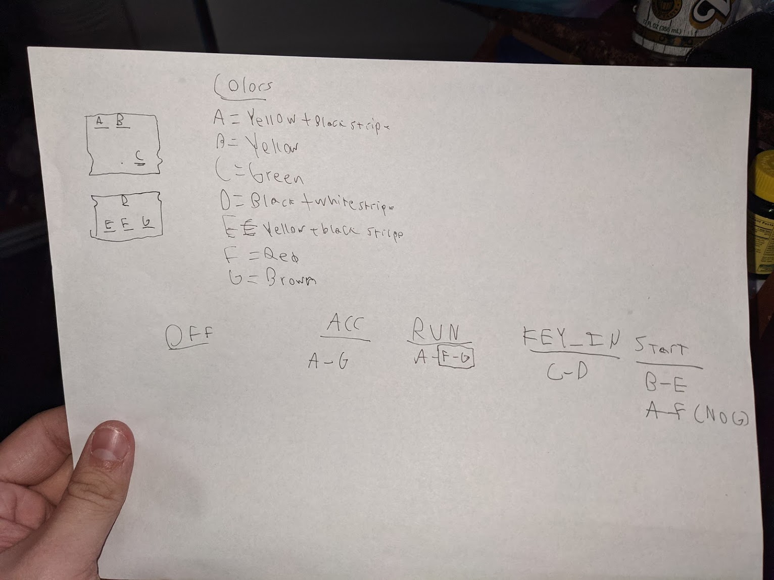
I just wrote down what pins connected together, along with the colors of each wire, for when I was actually working under my dash.
This also told me the relay count I needed for the switch handling itself. I went with 5 to be safe, to handle every little connection at each key position, just in case.
Design Decisions
Now that I knew my design constraints, I could get to work designing a board. I decided on a few things early on.
- ATmega328P as my microcontroller. I have a lot of experience with Arduino Unos, there’s a ton of documentation on the 328P, and it’s fairly low cost. I wanted something with decent oomf to handle the NFC reading, and potentially add an I2C screen down the line.
- All voltage conversion done on the board. I didn’t want to have to wire up some cruddy voltage regulator, so it had to be included in the board as well.
- All external parts, buttons, LEDs, etc., had to be socketed. I wanted to avoid soldering in my car all I could, so I wanted to be able to easily pull everything off of the board if I needed to swap, or do a minor repair. I also decided to socket my 328P, as it was cheap, and just overall a good idea.
- This is minor thing, but I wanted to have it be fused, and I wanted to use an automotive fuse. If somehow a fuse were to blow while I was on the road, I can grab a spare from the fusebox. This wasn’t a big deal, as through-hole automotive fuse holders are easy to find.
- I wanted to use the PN532 as my NFC controller. I’ve used it a good bit, it’s cheap, and the Adafruit libraries are good for it. I decided to go with the HiLetGo PN532 breakout, for ~$10. I had used them before, and they’re cheap but reliable.
- Everything should be easily reversible, with minimal spare parts needed to downgrade.
- I wanted everything to be controlled by a master power switch. Sometimes I don’t drive for weeks at a time, so it’s important to be able to cut all battery draw easily.
- I wanted to use I2C for the PN532. I had experience with I2C, it took the least number of wires, and it would be very easy to add additional devices on the same bus.
Security Bypassing
For my particular car, ignition security consists of the GM PASSKEY 3 transponder immobilizer system, along with a physical steering lock inside the ignition switch.
Thankfully, the aftermarket remote start people had already thought of a good transponder bypass solution.
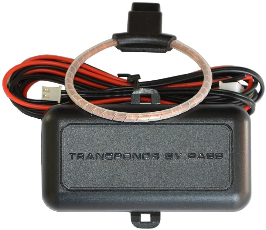
This is a transponder bypass module, made by the company BANVIE. This particular model appears to have been discontinued a few days after I bought it, but there are tons of models very similar.
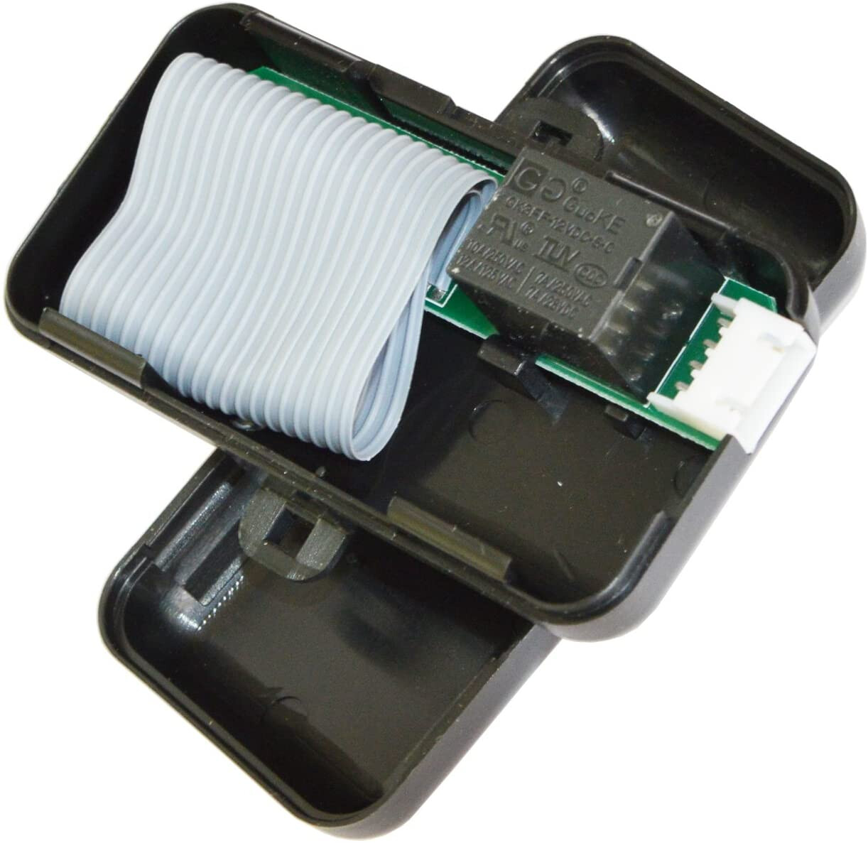
It consists of an inner compartment with an antenna that you slip your transponder key into (or just the chip from the top of the key), along with an antenna loop that goes around the immobilizer ring. It just takes 12 volts as well. I decided to add another relay to my board, to allow me to not turn on the bypass module until authentication had occurred.
Now, there was a problem, I only had a single key. So, I went to a local hardware store (Ace hardware), and had a spare key made without the transponder (told them I wanted a door key). Cost me $4, and this allowed me to have a key to use in the ignition or in the doors, while keeping my original key intact.
That spare key is needed for the next portion, defeating the steering lock. This is done by a beefy bowden cable, that gets mechanically pulled when the key is in the run position. I could have tried modding the cable itself, maybe adding a spacer to keep it disengaged. However, instead I just took another note from the remote start folks, and decided to file down my spare key to the point where pliers are needed to turn of remove it, and keep it in the ignition on the run position. The actual switch would be electrically disconnected, with wiring behind multiple layers of shields, so there wasn’t any real worry about keeping the steering lock disengaged. Car thefts aren’t really a thing in my area, either. Someone will break your window if you leave anything valuable inside, but no one is hot-wiring cars tbh.
Part Selection
For my relays, I knew I wanted a name brand, for reliability. My process for selecting was just going to Digi-Key (who I had chosen due to their excellent BOM tools and their part selection), filling in my main requirements, and sorting by the one with the most stock available. I wanted common well known models, so for the most part, I did this for everything. I decided to go with the Omron G5V-1-DC5 relay, as I knew I needed something with a 5V coil voltage, and the switching voltage and current were just fine for what I was doing. I knew that they were just carrying signals, not any real current.
For my voltage regulator, I chose the cheapest common 5V regulator I could find that supported 12V, and had enough current capability (1.5 amps in this case). I went for the L7805ACV.
For my connectors, I ended up just buying a kit on amazon. It came with a good ratcheting crimper, along with a bunch of JST-XH connectors. I originally designed this for specific locking connectors, so the pitch didn’t match. I was able to make this work for the 2 pin connectors, but the 5 pin connector ended up being replaces with a hardline connection unfortunately.
Board Design
For designing my board, I decided to go with KiCad. If I was gonna learn software for this, I wanted it to be open source, and able to run on Linux. KiCad was the obvious choice. KiCad is really nice, and overall I enjoyed learning and using it.
I started by making a schematic. I’ll post a screenshot of the “final” schematic. There are some issues here, I’ll address them later in the write-up.
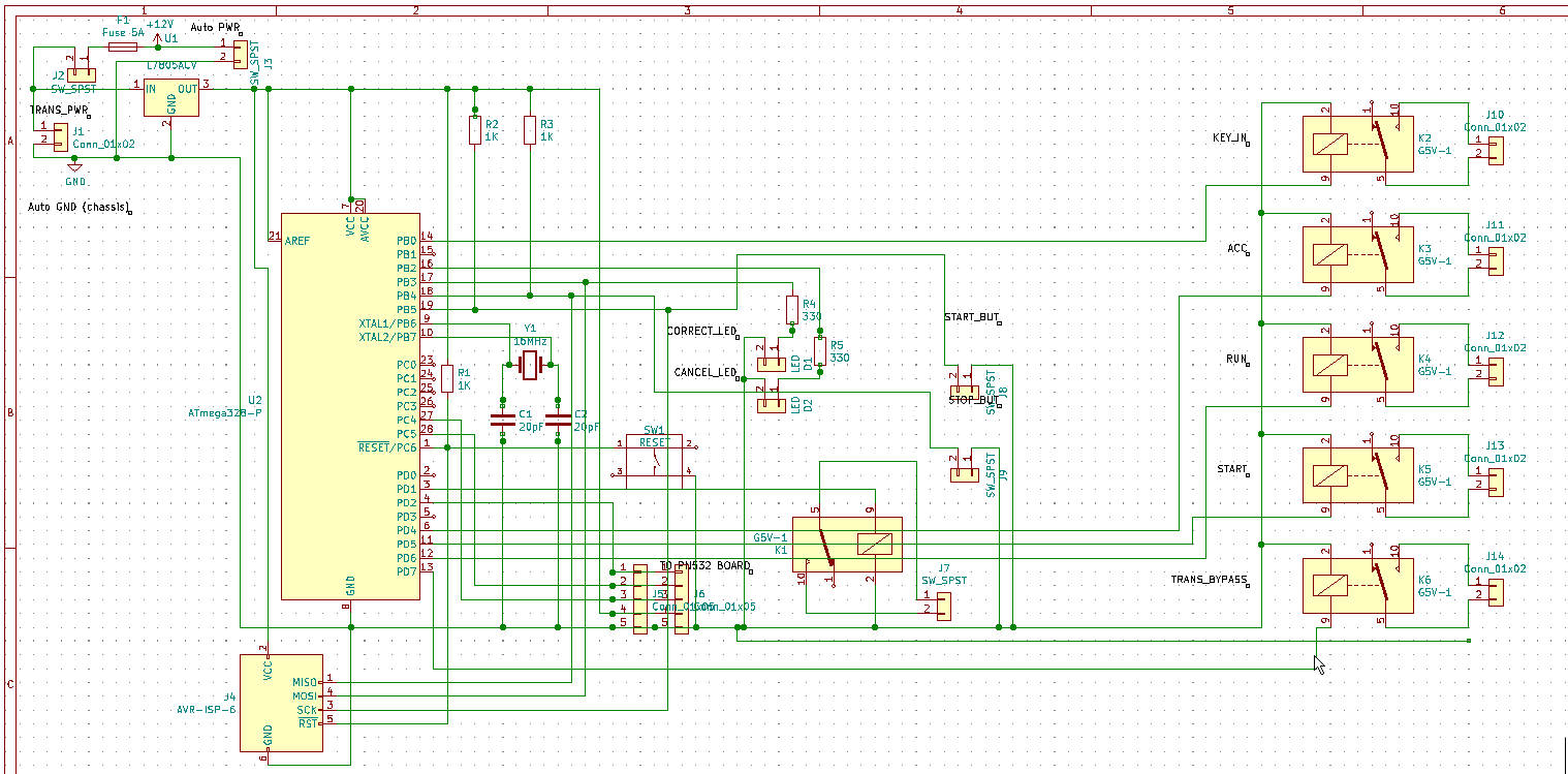
Getting the initial schematic done took a few hours, and from there I refined it for a few days, whenever I thought of anything new I forgot. A helpful resource is looking up 328P breadboard examples, as that can tell you a lot of what is necessary at the core of things. Again, anyone with much experience will likely notice a few things wrong here, I’ll talk about those later.
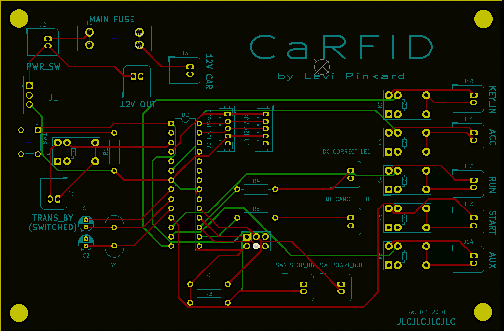
On this screenshot, red traces are on the front, and green are on the back. I used a 2 layer PCB, and tried to avoid all of the traces I could on the 2nd layer, as I didn’t want to create any ground loops.
This is the layout of the first revision. For linking the schematic to actual physical objects, you need footprints. I found these rather easily by just googling the part name + “KiCad footprint”.
I knew vaguely what I was doing for laying things out, but there will likely be some things spotted by more eagle-eyed members with circuit board design experience.
Fabrication
I decided to go with JLCPCB for making my boards. They have a decent track record, they’re insanely cheap for 2 layer boards, and the shipping to the US was decently cheap considering the speed.
It ended up taking 6 days from order to arrival, with 3 of those days being for fabrication itself.
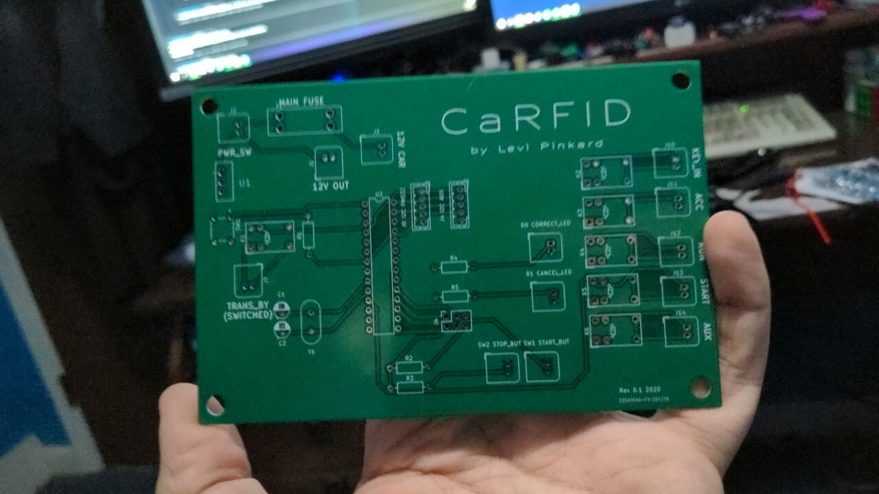
They ended up being ~$23 including shipping for the 5 boards I had made.
They looked great in my opinion, and got one soldered up as soon as I got them (the Digi-Key order came a day or two earlier).
Programming
This bit isn’t going to be very detailed at the moment unfortunately. I based the code off of the code I used for my NFC safe project a month or so back. I started programming the second I had a final board design, as I knew the pinouts of everything, and I knew how it needed to function. It just stores some UIDs in the program itself, authenticates, enables the transponder bypass + accessory mode + key in, then when the start button is pushed, it runs through the ignition sequence one by one, starting for a period of 2 seconds or so. I added my Spark 2, xSIID, and NExT, so any of them can be scanned for authentication.
After a bit more testing and refinement I’ll upload the commented code to github, and link it here.
Board Assembly & Initial Testing
The board went together well, besides for the issue with pin pitch mentioned earlier. I decided to solder the lines for the PN532 directly to the board, and add a connector further up on the cable.

I had purchased a Sparkfun USBtiny ISP programmer, and added a 6 pin ISP header to the board to allow me to program the 328P while it was in the system. I connected the programmer, tried to flash some blink code via avrdude, and it errored out. I decided to pull the micro, plop it in an UNO I had, and program it via ISP that way (since there was no bootloader from the factory). I programmed the micro, and threw it back in the board. The blink test was working, it could flash one of the LEDs (specifically my “correct” LED). However, there was another issue, it was running way too slow. Like, crazy slow. I was running it with a 16MHz crystal, which is pretty standard, but the LED was blinking over 10X slower than it should be.
After some googling, I realized that the 328P is set by default to use it’s internal 8MHz clock, and divide it by 8. This meant that the micro was running at 1MHz, not 16. 16X slower than desired. Fun. Thankfully this is set with an internal software fuse, that I was able to set using avrdude. This fixed the clock issue, but I still couldn’t program the 328P via my own board.
I decided to look at the ISP pinout of the UNO, and compare it to mine, to double check. My schematic was fine, identical to an Uno. However, I then looked at my actual PCB design. It turns out, the footprint I had found online was flipped horizontally ![]() It’s as if it was meant to be used from the other side of the board. My bad for not checking it, should always check the pinouts of footprints. I threw together an adapter using my new crimping kit, flipping everything, and now it worked fine, and I could program the board without constantly popping out the micro.
It’s as if it was meant to be used from the other side of the board. My bad for not checking it, should always check the pinouts of footprints. I threw together an adapter using my new crimping kit, flipping everything, and now it worked fine, and I could program the board without constantly popping out the micro.
I then actually threw on the code for the board that I had written earlier, so I could test the relays. To my confusion, the relays would turn on, but not off. They wouldn’t disengage. I then wrote a little program to test each relay, and the same story.
![]()
![]()
![]()
I’m sure some of you already spotted it earlier in the write-up, but I had FORGOTTEN the pull-down resistors for each relay.
![]()
![]()
![]()
This wasn’t a massive deal, I threw some bodge resistors on the bottom side of the board. Not ideal, but after testing again, each relay was actuating fine.
I then was ready to actually put this thing in my car.
First Day of Install
Unfortunately, I do not have any photos or anything from this section. It was windy, below 30 fahrenheit, and ~1am.
I started by disconnecting the battery, and running my power and ground wires. I just went to my passenger side fuse box and tacked on my power wire to a section that I thought had some overhead left. I knew from testing with a benchtop PSU that my board used ~.1 amps, so I didn’t need much power. I decided to tack onto the fuse for the keyless entry system, as the fuse rating seemed considerably higher than that system needed. My board itself was fused too, so I’m not very worried about safety for this portion. My ground wire was just tacked onto the chassis via an exposed bolt and a crimped wire lug. I then ran these over to the radio compartment via the glove box.
Then, I just tested the transponder bypass. Through my key in it, gave it power, and tested starting my car with the door key. Worked great, much easier than I expected.
For connecting into my ignition switch, I ended disconnecting the connectors for the switch, then doing a soldered T splice for every ignition wire. This would be tedious, but it would give a good connection, and I would only have to do it once. I used a 10-wide ribbon cable, to allow me to connect my 2 wires for each relay. I used a set of automatic wire strippers, which I bought for this build. I highly, highly recommend getting a set. They made splicing into the wire super easy, and overall were great for this project (being able to set a strip length is great for crimped connectors).
I then ran that ribbon cable up through a hole that already existed between the rear of the dash and the radio compartment. The hole contained a vent hose, but there was more than enough spare room to get my cable through. Once I got it through, I crimped each pair of cables with a connector, and plugged them into the board.
I then crossed my fingers, reconnected the battery, and tested it.
ACC and RUN seemed to work, but no matter what I tried, it wouldn’t even try to crank. I messed around with it for about 2 hours, then gave up, realizing that I was too tired and sore to do much more that night. I removed my board, plugged the original ignition switch back in, and tested it. Still worked fine, got everything buttoned up, and went back inside. However, in the process of removing the key from the bypass, I accidentally swiped the entire antenna with my screwdriver. I saw that one portion of the antenna had broken. Whoops. If I needed to buy a new one, this wasn’t a huge deal, it was $10 total. Decided I would take a closer look at it later, when I got back inside. I decided I would finish it tomorrow.
Second Day of Install
“Finish it tomorrow” turned into nearly 2 weeks. Whoops. I’m a bigger guy, with a few health issues, and the first day of work ended up making me bedridden for about 4 days, barely able to move. My knees were sore from kneeling on a concrete driveway, and my back and arms hurt from all of the working and soldering under the dash. I also needed a small mental vacation, just to lay back and watch some TV for a few days. Ended up watching all of The Boys, highly recommended ![]()
I only ended up getting back to it tonight, after Christmas and New Years had finished. I started by powering up my board, and testing each relay for each position. Immediately found an error, ACC wasn’t being disabled when I went to start. That probably contributed to some of my issues, was a single line of code changed. I then double checked my pinout, and discovered that my RUN and start had been a bit swapped around. I started by fixing my bypass module. Thankfully, the only break was in the very start of the antenna. It had snapped right at the solder joint. I was able to easily desolder the little bit of pin that was left (~1mm, nothing big) and resoldered it. Hoped this had fixed it. Went back out tonight, and thankfully most of the work had already been done on the last attempt. Got the ignition switch disconnected, my board plugged back in with the fixed connections and fixed code. Reconnected the battery, tried it, and BLAMMO, started right up. Everything seemed to work, except for my radio. I’ll address that more in a below section. This is the end of the work to this point, and resulted in the video at the start of the post. I took it for a drive around the neighborhood too, and it drove fine, no issues at all ![]()
Plans for the near future
The first thing is figuring out my radio issue. It’s a decent few steps to get to my radio, so I didn’t feel like looking at it tonight. My guess is simply the connector being loose, or a wire came loose. The radio install isn’t the best, it’s a bit spotty (pre-existing after-market from when I got the car). Some connections aren’t soldered, the power wire could have easily just come undone (it was ran seperately to the accessory relay).
If that’s not the case, it could be an issue with my board not engaging the accessory relay. I have a few thoughts on this, and a few things I could try if this is the case. I don’t think this is the case though, as accessory worked in the prior day of testing, and I even tried the radio.
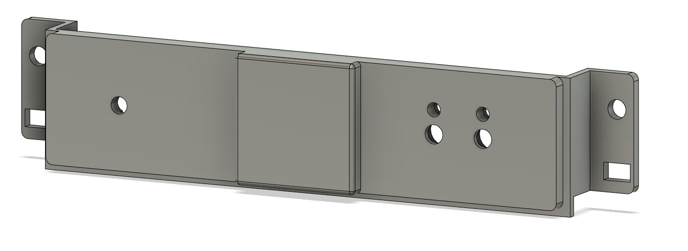
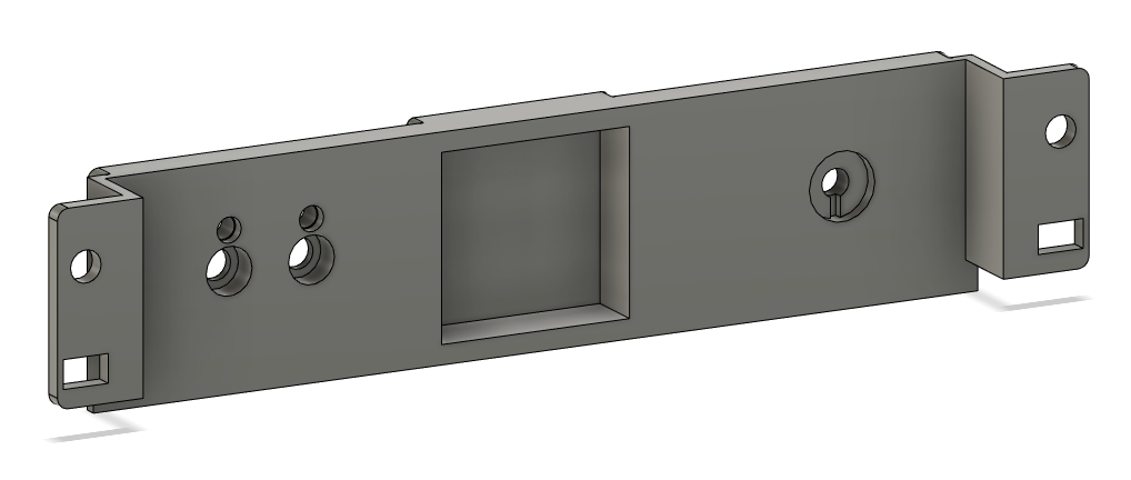
Next is essential as well, and that’s designing the front panel. This should only take me an hour or so in Fusion 360. I already modified the dash kit for my radio to allow me to install my panel in that spot. Normally, the bottom of my radio area has a shelf/cubby that I cut out. It’s only ~$20-30 for a whole new dash kit for my car, so I can always replace that later, didn’t care about modifying it.
I’m doing some commissioned 3D printing for the next day or two, but I can get the design printed and installed after that.
Lastly, I think it would be really neat to add an OLED I2C screen. This would allow me to show what implant was scanned, current status of each relay, current key position, etc. Could always have some nifty animations, too.
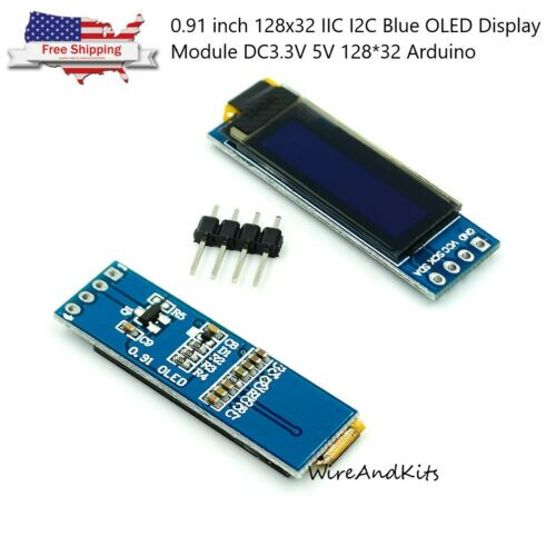
I bought one for $5 on ebay, might add it down the line, might not. Think it would be a cool addition, but not necessary for core functionality. I did already add a second I2C connector spot on the board, for just this purpose.
If you made it all the way through, congrats, it’s a long read. I will likely revise this a bit down the line, as I’ve been up for a long time on very little sleep, and feel like this isn’t my best writing (just hit 6am here).
In the next day or two I’ll post the code and KiCad files on GitHub, and I’ll post those links here. I’ll also post the Digi-Key BOM, I’m fixing some parts right now though, as I changed a few components at the last minute. In the next week or two I will also likely upload a new revision of the PCB, fixing the issues with this version (the flipped ISP connector & adding pull-down resistors for the relays, as mentioned above).
EDIT: Added better video (again).
EDIT: Here’s the link to the repo with the KiCad files, and the code.
The authentication bit is admittedly a bit hacky, will probably clean it up a bit later. It does work, but adding new UIDs is quite annoying.